Toyota Venza: Data Signal Circuit between Navigation Receiver Assembly and Stereo Jack Adapter
DESCRIPTION
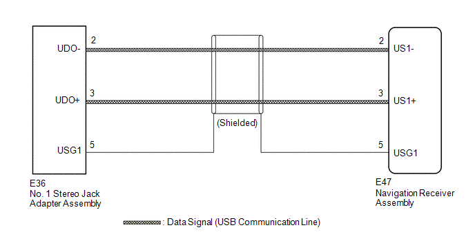
The No. 1 stereo jack adapter assembly sends the sound data signal or image data signal from a USB device to the navigation receiver assembly via this circuit.
WIRING DIAGRAM
PROCEDURE
|
1. |
CHECK HARNESS AND CONNECTOR (NAVIGATION RECEIVER ASSEMBLY - NO. 1 STEREO JACK ADAPTER ASSEMBLY) |
|
(a) Disconnect the E47 navigation receiver assembly connector. |
|
(b) Disconnect the E36 No. 1 stereo jack adapter assembly connector.
(c) Measure the resistance according to the value(s) in the table below.
Standard Resistance:
|
Tester Connection |
Condition |
Specified Condition |
|---|---|---|
|
E47-2 (US1-) - E36-2 (UDO-) |
Always |
Below 1 Ω |
|
E47-3 (US1+) - E36-3 (UDO+) |
Always |
Below 1 Ω |
|
E47-5 (USG1) - E36-5 (USG1) |
Always |
Below 1 Ω |
|
E47-2 (US1-) - Body ground |
Always |
10 kΩ or higher |
|
E47-3 (US1+) - Body ground |
Always |
10 kΩ or higher |
|
E47-5 (USG1) - Body ground |
Always |
10 kΩ or higher |
|
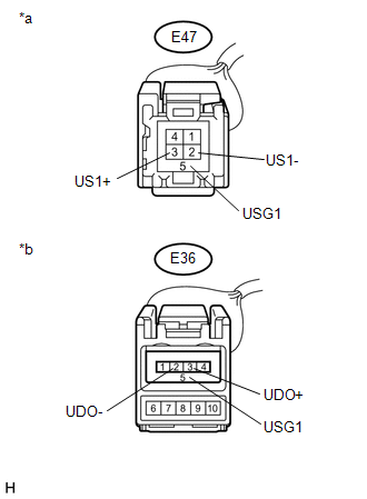
*a |
Front view of wire harness connector (to Navigation Receiver Assembly) |
|
*b |
Front view of wire harness connector (to No. 1 Stereo Jack Adapter Assembly) |
| OK | .gif) |
PROCEED TO NEXT SUSPECTED AREA SHOWN IN PROBLEM SYMPTOMS TABLE |
| NG | |
REPAIR OR REPLACE HARNESS OR CONNECTOR |
 Data Signal Circuit between Navigation Receiver Assembly and Extension Module
DESCRIPTION
The stereo component tuner assembly sends the image data signal to the navigation
receiver assembly via this circuit.
WIRING DIAGRAM
PROCEDURE
1.
CHECK NAVIG ...
 Mute Signal Circuit between Navigation Receiver Assembly and Stereo Component
Amplifier
Mute Signal Circuit between Navigation Receiver Assembly and Stereo Component
Amplifier
DESCRIPTION
This circuit sends a signal to the stereo component amplifier assembly to mute
noise. Due to this, the noise produced by changing the sound source ceases.
If there is an open in the ci ...
Other materials about Toyota Venza:
Seat Memory Switch
Components
COMPONENTS
ILLUSTRATION
Removal
REMOVAL
PROCEDURE
1. REMOVE FRONT DOOR INSIDE HANDLE BEZEL PLUG LH
2. REMOVE POWER WINDOW REGULATOR MASTER SWITCH ASSEMBLY WITH FRONT DOOR ARMREST
BASE PANEL
3. REMOVE COURTESY LIGHT ASSEMBLY
...
Occupant Classification System Malfunction (B1650/32)
DESCRIPTION
The occupant classification system circuit consists of the center airbag sensor
assembly and occupant classification system.
If the center airbag sensor assembly receives signals from the occupant classification
ECU, it determines whether the ...
Disassembly
DISASSEMBLY
PROCEDURE
1. REMOVE BREATHER PLUG HOSE
(a) Using a screwdriver, remove the No. 2 breather plug (ATM) from the
transaxle case sub-assembly.
(b) Using a screwdriver, remove ...

0.1724