Toyota Venza: On-vehicle Inspection
ON-VEHICLE INSPECTION
PROCEDURE
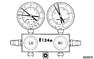
1. INSPECT REFRIGERANT PRESSURE WITH MANIFOLD GAUGE SET
HINT:
This is a method where a manifold gauge set is used to help locate the problem.
(a) Read the manifold gauge pressure when the following conditions are met:
Test conditions:
- Temperature at the air inlet with the switch set at RECIRC is 30 to 35°C (86 to 95°F).
- The engine is running at 1500 rpm.
- The blower speed control switch position is at "HI".
- The temperature control dial position is at "COOL".
- The A/C switch is on.
- Doors are fully open.
- The ignition switch is in a position that enables the A/C compressor to run.
|
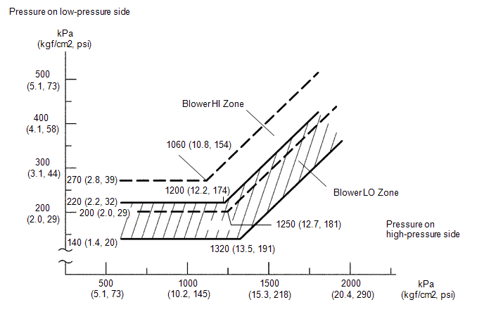
(1) Normally functioning refrigeration system Gauge Reading
|
|
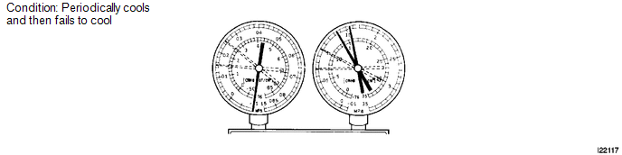
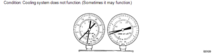
(2) Moisture is present in the refrigeration system.
|
Symptom |
Probable Cause |
Diagnosis |
Corrective Action |
|---|---|---|---|
|
During operation, pressure on low pressure side cycles between normal and vacuum |
|
|
|
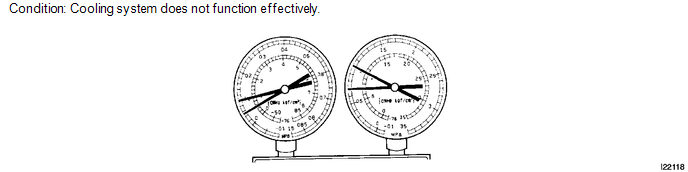
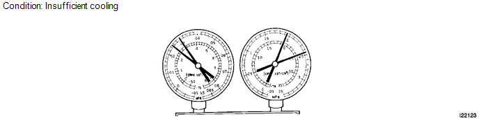
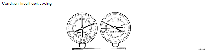
(3) Insufficient cooling
|
Symptom |
Probable Cause |
Diagnosis |
Corrective Action |
|---|---|---|---|
|
Gas leaks from the refrigeration system |
|
|
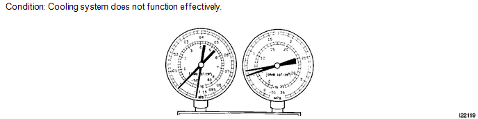
(4) Poor circulation of refrigerant
|
Symptom |
Probable Cause |
Diagnosis |
Corrective Action |
|---|---|---|---|
|
Refrigerant flow is obstructed by dirt inside the pipes of the condenser core |
Receiver is clogged |
Replace condenser |
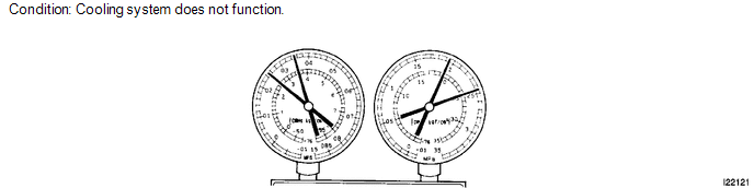
(5) Refrigerant does not circulate.
|
Symptom |
Probable Cause |
Diagnosis |
Corrective Action |
|---|---|---|---|
|
|
Refrigerant does not circulate |
|
(6) Refrigerant is overcharged or cooling effectiveness of condenser is insufficient.
|
Symptom |
Probable Cause |
Diagnosis |
Corrective Action |
|---|---|---|---|
|
|
|
|
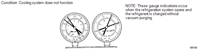
(7) Air is present in the refrigeration system.
|
Symptom |
Probable Cause |
Diagnosis |
Corrective Action |
|---|---|---|---|
|
Air in system |
|
|
(8) Expansion valve malfunction
|
Symptom |
Probable Cause |
Diagnosis |
Corrective Action |
|---|---|---|---|
|
Expansion valve may be stuck |
|
Check expansion valve |
(9) Insufficient compressor compression
|
Symptom |
Probable Cause |
Diagnosis |
Corrective Action |
|---|---|---|---|
|
Internal leak in compressor |
|
Replace compressor |
Gauge readings (Reference)
 Refrigerant
...
 Replacement
REPLACEMENT
PROCEDURE
1. RECOVER REFRIGERANT FROM REFRIGERATION SYSTEM
(a) Start up the engine.
(b) Turn the A/C switch on.
(c) Operate the cooler compressor at an engine speed of approximately 1 ...
Other materials about Toyota Venza:
Setting up the displays
Press the “SETUP” button while the
vehicle is stopped.
The “Custom Settings” screen is displayed on the multi-information display.
If left idle for approximately 10 seconds, the display will revert to the previous
screen.
Select “Display / ...
Reassembly
REASSEMBLY
CAUTION / NOTICE / HINT
NOTICE:
When using a vise, do not overtighten it.
PROCEDURE
1. INSTALL STEERING LOCK ACTUATOR ASSEMBLY (w/ Smart Key System)
(a) Secure the steering column assembly in a vise.
(b) Temporarily install the ste ...
Reassembly
REASSEMBLY
CAUTION / NOTICE / HINT
HINT:
Use an overhaul stand as necessary.
PROCEDURE
1. INSTALL DIFFERENTIAL RING GEAR
(a) Clean the contact surfaces of the rear differential case sub-assembly and
differential ring gear.
(b) Heat the differential ri ...

0.1216