Toyota Venza: Removal
REMOVAL
PROCEDURE
1. REMOVE COOL AIR INTAKE DUCT SEAL
.gif)
2. REMOVE INLET NO. 2 AIR CLEANER
3. REMOVE AIR CLEANER CAP WITH HOSE
4. REMOVE AIR CLEANER CASE
5. REMOVE AIR CLEANER BRACKET
|
(a) Separate the wire harness clamp. |
|
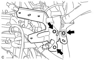
(b) Remove the 3 bolts and air cleaner bracket.
6. REMOVE PARK/NEUTRAL POSITION SWITCH ASSEMBLY
|
(a) Remove the clip from the transmission cable bracket. |
|
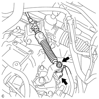
(b) Remove the nut and transmission control cable from the transmission control shaft lever.
(c) Disconnect the connector from the park/neutral position switch.
|
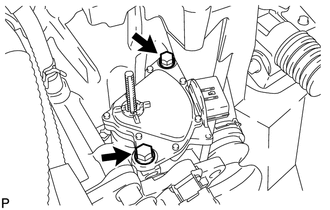
(d) Remove the nut, washer and transmission control shaft lever from the control shaft. |
|
.png)
|
(e) Remove the 2 bolts and park/neutral position switch from the control shaft. NOTICE: Before removing the park/neutral position switch, remove any dirt or rust on the installation portion of the control shaft. Be sure to remove the switch straight along the shaft while being careful not to deform the plate spring that supports the shaft. If the plate spring is deformed, the park/neutral position switch cannot be reinstalled correctly. |
|
 On-vehicle Inspection
ON-VEHICLE INSPECTION
PROCEDURE
1. INSPECT PARK/NEUTRAL POSITION SWITCH ASSEMBLY OPERATION
(a) Apply the parking brake.
(b) Turn the ignition switch to ON.
(c) Depress the brake pedal and check t ...
 Inspection
INSPECTION
PROCEDURE
1. INSPECT PARK/NEUTRAL POSITION SWITCH ASSEMBLY
(a) Measure the resistance according to the value(s) in the table below
when the shift lever is moved to each po ...
Other materials about Toyota Venza:
Removal
REMOVAL
CAUTION / NOTICE / HINT
NOTICE:
Release the vacuum from the booster by depressing the brake pedal several times.
Then remove the brake master cylinder from the brake booster.
PROCEDURE
1. DRAIN BRAKE FLUID
NOTICE:
If brake fluid leaks onto any ...
Light bulbs
You may replace the following bulbs yourself. The difficulty level of replacement
varies depending on the bulb. If necessary bulb replacement seems difficult to perform,
contact your Toyota dealer.
For more information about replacing other light bulbs, c ...
Inspection
INSPECTION
PROCEDURE
1. INSPECT STEERING PAD SWITCH ASSEMBLY
(a) Measure the resistance according to the value(s) in the table below.
Standard Resistance:
Tester Connection
Condition
Specified Condition
...

0.1453