Toyota Venza: Inspection
INSPECTION
CAUTION / NOTICE / HINT
HINT:
Use the same procedure for the intake side and exhaust side.
PROCEDURE
1. INSPECT CAMSHAFT TIMING OIL CONTROL VALVE ASSEMBLY
|
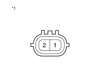
(a) Measure the resistance according to the value(s) in the table below. Standard Resistance:
If the result is not as specified, replace the oil control valve assembly. Text in Illustration
|
|
|
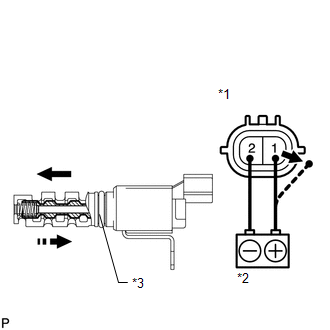
(b) Connect the positive (+) lead from a battery to terminal 1 and the negative (-) lead to terminal 2, and check the movement of the valve. OK:
NOTICE: Confirm that the valve moves freely and does not stick in any position. If necessary, replace the camshaft timing oil control valve assembly. HINT: Accumulation of foreign matter can cause minor pressure leaks. Minor pressure leaks will cause the camshaft to advance or retard, and this will cause a DTC to be set. Text in Illustration
|
|
 Removal
REMOVAL
PROCEDURE
1. REMOVE NO. 1 ENGINE COVER SUB-ASSEMBLY
2. REMOVE CAMSHAFT TIMING OIL CONTROL VALVE ASSEMBLY (for Exhaust Side)
(a) Disconnect the oil control valve connector.
...
 Installation
INSTALLATION
PROCEDURE
1. INSTALL CAMSHAFT TIMING OIL CONTROL VALVE ASSEMBLY (for Exhaust Side)
(a) Apply a light coat of engine oil to a new O-ring, and install it
to the oil contro ...
Other materials about Toyota Venza:
Vehicle load limits
Vehicle load limits include total load capacity, seating capacity, Trailer
Weight Rating (TWR) and cargo capacity.
- Total load capacity (Vehicle capacity weight):
Total load capacity means the combined weight of occupants, cargo and luggage.
&nbs ...
Vehicle Speed Signal Malfunction (C1541)
DESCRIPTION
The power steering ECU receives vehicle speed signals from the brake actuator
assembly (skid control ECU) via CAN communication. The ECU provides appropriate
assisting force in accordance with the vehicle speed, based on the signals.
...
Front Occupant Classification Sensor RH Collision Detection (B1786)
DESCRIPTION
DTC B1786 is output when the occupant classification ECU receives a collision
detection signal sent by the front occupant classification sensor RH if an accident
occurs.
DTC B1786 is also output when the front seat assembly RH is subjected to ...

0.1738