Toyota Venza: Short in Front Pretensioner Squib RH Circuit (B1900/73-B1903/73)
DESCRIPTION
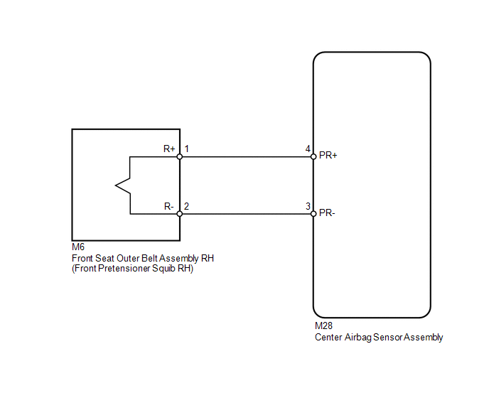
The front pretensioner squib RH circuit consists of the center airbag sensor assembly and front seat outer belt assembly RH.
The center airbag sensor assembly uses this circuit to deploy the seat belt pretensioner when deployment conditions are met.
These DTCs are stored when a malfunction is detected in the front pretensioner squib RH circuit.
|
DTC No. |
DTC Detection Condition |
Trouble Area |
|---|---|---|
|
B1900/73 |
|
|
|
B1901/73 |
|
|
|
B1902/73 |
|
|
|
B1903/73 |
|
|
WIRING DIAGRAM
CAUTION / NOTICE / HINT
HINT:
- Perform the simulation method by selecting check mode (Signal Check)
using the Techstream (See page
.gif) ).
).
- After selecting check mode (Signal Check), perform the simulation method
by wiggling each connector of the airbag system or driving the vehicle on
a city or rough road (See page ).
PROCEDURE
|
1. |
CHECK CONNECTORS |
|
(a) Turn the ignition switch off. |
|
.png)
(b) Disconnect the cable from the negative (-) battery terminal, and wait for at least 90 seconds.
(c) Check that the connectors are properly connected to the front seat outer belt assembly RH and center airbag sensor assembly.
OK:
The connectors are properly connected.
HINT:
If the connectors are not connected securely, reconnect the connectors and proceed to the next inspection.
(d) Disconnect the connectors from the front seat outer belt assembly RH and center airbag sensor assembly.
(e) Check that the terminals of the connectors are not damaged.
OK:
The terminals are not deformed or damaged.
(f) Check that the No. 2 floor wire connector (on the front seat outer belt assembly RH side) is not damaged.
OK:
The lock button is not disengaged, and the claw of the lock is not deformed or damaged.
(g) Check that the short spring for the No. 2 floor wire with the activation prevention mechanism is not deformed or damaged.
OK:
The short spring is not deformed or damaged.
Text in Illustration|
*1 |
Front Pretensioner Squib RH |
|
*2 |
Center Airbag Sensor Assembly |
|
*3 |
No. 2 Floor Wire |
| NG | .gif) |
REPLACE NO. 2 FLOOR WIRE |
|
.gif)
|
2. |
CHECK FRONT SEAT OUTER BELT ASSEMBLY RH (FRONT PRETENSIONER SQUIB RH) |
|
(a) Connect the connector to the center airbag sensor assembly. |
|
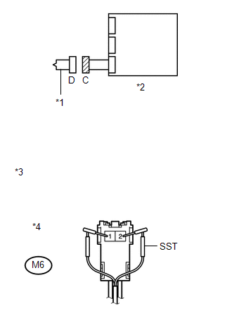
(b) Connect SST (resistance 2.1 Ω) to connector C.
CAUTION:
Never connect an electrical tester to the front seat outer belt assembly RH (front pretensioner squib RH) for measurement, as this may lead to a serious injury due to airbag deployment.
NOTICE:
- Do not forcibly insert SST into the terminals of the connector when connecting.
- Insert SST straight into the terminals of the connector.
SST: 09843-18061
(c) Connect the cable to the negative (-) battery terminal.
(d) Turn the ignition switch to ON, and wait for at least 60 seconds.
(e) Clear the DTCs stored in memory (See page
).
(f) Turn the ignition switch off.
(g) Turn the ignition switch to ON, and wait for at least 60 seconds.
(h) Check for DTCs (See page ).
OK:
DTC B1900, B1901, B1902, B1903 or 73 is not output.
Text in Illustration|
*1 |
Front Pretensioner Squib RH |
|
*2 |
Center Airbag Sensor Assembly |
|
*3 |
Front view of wire harness connector (to Front Seat Outer Belt Assembly RH) |
|
*4 |
Connector C |
HINT:
Codes other than DTCs B1900, B1901, B1902, B1903 and 73 may be output at this time, but they are not related to this check.
| OK | |
REPLACE FRONT SEAT OUTER BELT ASSEMBLY RH |
|
|
3. |
CHECK NO. 2 FLOOR WIRE (FRONT PRETENSIONER SQUIB RH CIRCUIT) |
|
(a) Turn the ignition switch off. |
|
(b) Disconnect the cable from the negative (-) battery terminal, and wait for at least 90 seconds.
(c) Disconnect SST from connector C.
(d) Disconnect the No. 2 floor wire from the center airbag sensor assembly.
(e) Check for a short to B+ in the circuit.
(1) Connect the cable to the negative (-) battery terminal.
(2) Turn the ignition switch to ON.
(3) Measure the voltage according to the value(s) in the table below.
Standard Voltage:
|
Tester Connection |
Switch Condition |
Specified Condition |
|---|---|---|
|
M6-1 (R+) - Body ground |
Ignition switch ON |
Below 1 V |
|
M6-2 (R-) - Body ground |
Ignition switch ON |
Below 1 V |
(f) Check for an open in the circuit.
(1) Turn the ignition switch off.
(2) Disconnect the cable from the negative (-) battery terminal, and wait for at least 90 seconds.
(3) Measure the resistance according to the value(s) in the table below.
Standard Resistance:
|
Tester Connection |
Condition |
Specified Condition |
|---|---|---|
|
M6-1 (R+) - M6-2 (R-) |
Always |
Below 1 Ω |
(g) Check for a short to ground in the circuit.
(1) Measure the resistance according to the value(s) in the table below.
Standard Resistance:
|
Tester Connection |
Condition |
Specified Condition |
|---|---|---|
|
M6-1 (R+) - Body ground |
Always |
1 MΩ or higher |
|
M6-2 (R-) - Body ground |
Always |
1 MΩ or higher |
(h) Check for a short in the circuit.
(1) Release the activation prevention mechanism built into connector B (See page
).
(2) Measure the resistance according to the value(s) in the table below.
Standard Resistance:
|
Tester Connection |
Condition |
Specified Condition |
|---|---|---|
|
M6-1 (R+) - M6-2 (R-) |
Always |
1 MΩ or higher |
|
*1 |
Front Pretensioner Squib RH |
|
*2 |
Center Airbag Sensor Assembly |
|
*3 |
No. 2 Floor Wire |
|
*4 |
Front view of wire harness connector (to Front Seat Outer Belt Assembly RH) |
|
*5 |
Connector C |
| NG | |
REPLACE NO. 2 FLOOR WIRE |
|
|
4. |
CHECK CENTER AIRBAG SENSOR ASSEMBLY |
|
(a) Restore the released activation prevention mechanism of connector B to the original condition. |
|
.png)
(b) Connect the connectors to the front seat outer belt assembly RH and center airbag sensor assembly.
(c) Connect the cable to the negative (-) battery terminal.
(d) Turn the ignition switch to ON, and wait for at least 60 seconds.
(e) Clear the DTCs stored in memory (See page
).
(f) Turn the ignition switch off.
(g) Turn the ignition switch to ON, and wait for at least 60 seconds.
(h) Check for DTCs (See page ).
OK:
DTC B1900, B1901, B1902, B1903 or 73 is not output.
Text in Illustration|
*1 |
Front Pretensioner Squib RH |
|
*2 |
Center Airbag Sensor Assembly |
HINT:
Codes other than DTCs B1900, B1901, B1902, B1903 and 73 may be output at this time, but they are not related to this check.
| OK | |
USE SIMULATION METHOD TO CHECK |
| NG | |
REPLACE CENTER AIRBAG SENSOR ASSEMBLY |
 Short in Driver Side Knee Airbag Squib Circuit (B1860/64-B1863/64)
DESCRIPTION
The driver side knee airbag squib circuit consists of the center airbag sensor
assembly and driver side knee airbag assembly.
The center airbag sensor assembly uses this circuit to dep ...
 Short in Front Pretensioner Squib LH Circuit (B1905/74-B1908/74)
DESCRIPTION
The front pretensioner squib LH circuit consists of the center airbag sensor
assembly and front seat outer belt assembly LH.
The center airbag sensor assembly uses this circuit to depl ...
Other materials about Toyota Venza:
System Diagram
SYSTEM DIAGRAM
Transmitting ECU
(Transmitter)
Receiving ECU
Signal
Communication Method
ECM
Power Steering ECU
Engine speed signal
Engine variation inform ...
Camshaft Position "B" Actuator Circuit / Open (Bank 1) (P0013)
DESCRIPTION
The Variable Valve Timing (VVT) system adjusts the exhaust valve timing to improve
driveability. The engine oil pressure turns the VVT controller to adjust the valve
timing.
The camshaft timing oil control valve is a solenoid valve and switch ...
Malfunction in Deceleration Sensor (C0365/28,C1234/34,C1245/32,C1245/45)
DESCRIPTION
The skid control ECU receives signals from the yaw rate and acceleration sensor
via the CAN communication system.
The yaw rate sensor has a built-in acceleration sensor.
If there is trouble in the bus lines between the yaw rate and acceleratio ...

0.174