Toyota Venza: Removal
REMOVAL
CAUTION / NOTICE / HINT
HINT:
- Use the same procedure for the RH side and LH side.
- The procedure listed below is for the LH side.
PROCEDURE
1. PRECAUTION
HINT:
See page .gif)
2. DRAIN AUTOMATIC TRANSAXLE FLUID
HINT:
- for U660E: See page
- for U660F: See page
- for U760E: See page
- for U760F: See page
3. DRAIN TRANSFER OIL (for AWD)
4. REMOVE FRONT WHEELS
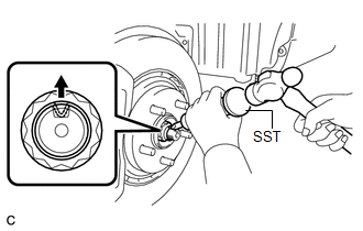
5. REMOVE FRONT AXLE SHAFT NUT
|
(a) Using SST and a hammer, release the staked part of the front axle shaft nut. SST: 09930-00010 NOTICE: Loosen the staked part of the nut completely, otherwise the threads of the drive shaft may be damaged. |
|
(b) While applying the brakes, remove the front axle shaft nut.
6. SEPARATE FRONT STABILIZER LINK ASSEMBLY
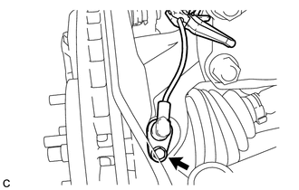
7. SEPARATE FRONT SPEED SENSOR
|
(a) Remove the bolt and separate the front speed sensor from the steering knuckle. |
|
|
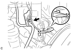
(b) Remove the bolt and clamp, and separate the front speed sensor and front flexible hose. |
|
8. SEPARATE TIE ROD ASSEMBLY
9. SEPARATE FRONT LOWER SUSPENSION ARM
10. SEPARATE FRONT AXLE ASSEMBLY
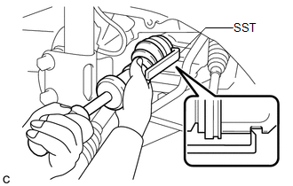
11. REMOVE FRONT DRIVE SHAFT ASSEMBLY LH
|
(a) Using SST, remove the front drive shaft assembly LH. SST: 09520-01010 SST: 09520-24010 09520-32040 NOTICE:
|
|
12. REMOVE FRONT DRIVE SHAFT ASSEMBLY RH (for 2WD)
|
(a) Remove the bearing bracket hole snap ring from the drive shaft bearing bracket. |
|
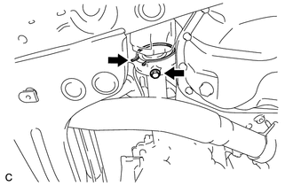
(b) Remove the bolt and front drive shaft assembly RH from the drive shaft bearing bracket.
NOTICE:
Do not damage the boot or oil seal.
13. REMOVE FRONT DRIVE SHAFT ASSEMBLY RH (for AWD)
|
(a) Remove the bearing bracket hole snap ring from the drive shaft bearing bracket. |
|
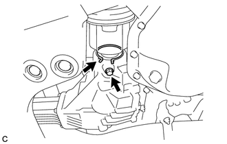
(b) Remove the bolt and front drive shaft assembly RH from the drive shaft bearing bracket.
NOTICE:
Do not damage the boot or oil seal.
 Components
COMPONENTS
ILLUSTRATION
ILLUSTRATION
ILLUSTRATION
ILLUSTRATION
ILLUSTRATION
...
 Disassembly
DISASSEMBLY
PROCEDURE
1. REMOVE FRONT DRIVE SHAFT HOLE SNAP RING (for LH Side)
(a) Using a screwdriver, remove the front drive shaft hole snap ring.
...
Other materials about Toyota Venza:
Diagnostic Trouble Code Chart
DIAGNOSTIC TROUBLE CODE CHART
If a trouble code is displayed during the DTC check, check the circuit listed
for the code in the table below (proceed to the page listed for that circuit).
HINT:
When DTC B1650/32 is detected as a result of troubleshooting f ...
Engine does not Start
DESCRIPTION
1. ENGINE START SYSTEM FUNCTION
(a) If the engine switch is pressed with the shift lever in P or N and the brake
pedal depressed, the power management control ECU determines that this is an engine
start request.
(b) The certification ECU (sm ...
Problem Symptoms Table
PROBLEM SYMPTOMS TABLE
HINT:
Use the table below to help determine the cause of problem symptoms. If multiple
suspected areas are listed, the potential causes of the symptoms are listed in order
of probability in the "Suspected Area" column of ...

0.1686