Toyota Venza: Parts Location
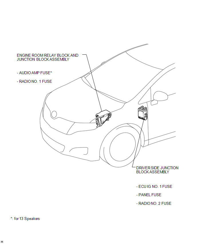
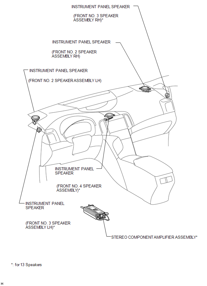
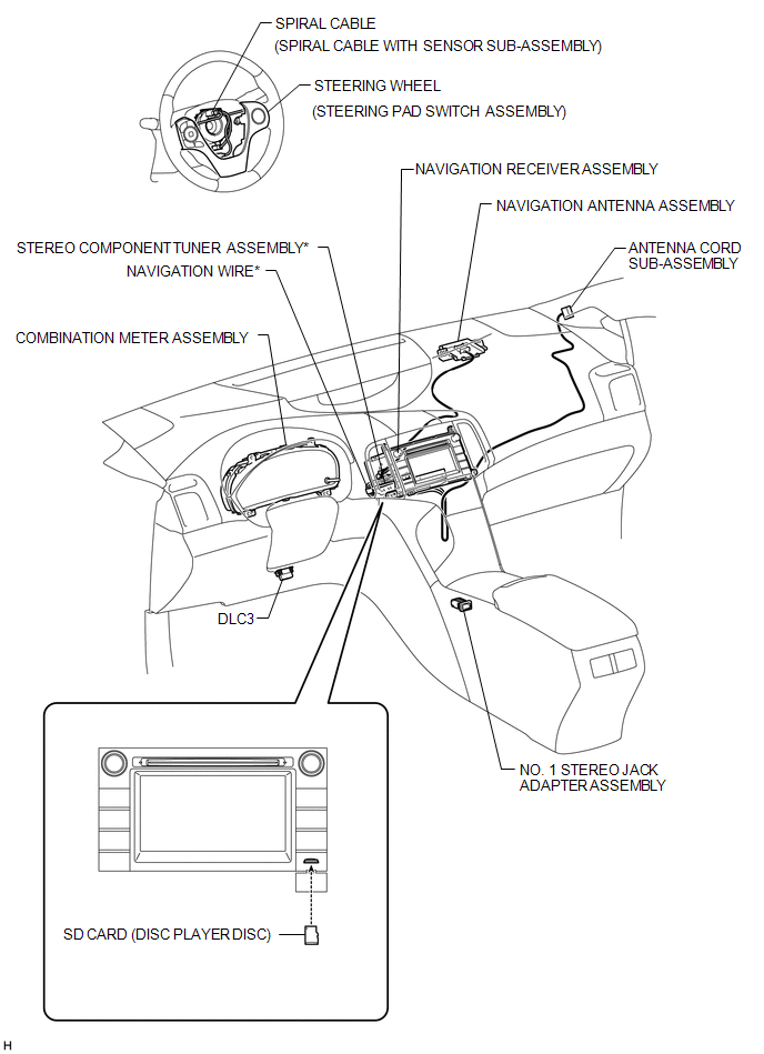
PARTS LOCATION
ILLUSTRATION
ILLUSTRATION
.png)
ILLUSTRATION

ILLUSTRATION
ILLUSTRATION

 Precaution
PRECAUTION
1. PRECAUTION FOR DISCONNECTING CABLE FROM NEGATIVE BATTERY TERMINAL
NOTICE:
After the ignition switch is turned off, the navigation receiver assembly
records various types o ...
Other materials about Toyota Venza:
Installing child restraints using a seat belt (child restraint lock function
belt)
- Rear-facing -- Infant seat/convertible seat
Place the child restraint system on the rear seat facing the rear of the vehicle.
Run the seat belt through the child restraint system and insert the plate into
the buckle. Make sure that the belt is ...
Power Back Door cannot be Closed Using the Power Back Door Closer Switch
DESCRIPTION
When the power back door cannot be closed using the power back door closer switch,
either of the following may be malfunctioning: 1) power back door closer switch
circuit or 2) power back door ECU (power back door motor unit).
WIRING DIAGRAM
...
Components
COMPONENTS
ILLUSTRATION
ILLUSTRATION
ILLUSTRATION
ILLUSTRATION
ILLUSTRATION
ILLUSTRATION
ILLUSTRATION
...

0.1329