Toyota Venza: System Description
SYSTEM DESCRIPTION
1. GENERAL
(a) Deceleration sensors used for the airbag system are installed on various parts on the vehicle and calculate the deceleration rate of each part during a collision.
(b) Depending on the situation, the center airbag sensor assembly sends a deployment signal to airbag and pretensioner based on the information from each sensor.
2. DEPLOYMENT CONDITION
(a) FRONTAL COLLISION
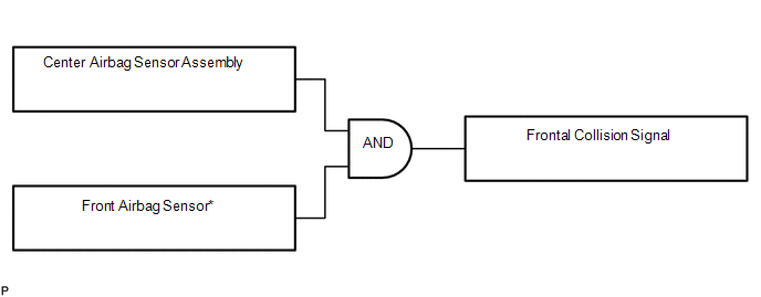
(1) Frontal collision signals are produced based on the information from the center airbag sensor assembly and front airbag sensors.
HINT:
*: In case of a frontal collision, the SRS ignition signal could be output with the deceleration sensor ON signal even without a signal from the front airbag sensors.
(2) Frontal collision signals are used to deploy the airbags and pretensioners except the side airbags.
(b) SIDE COLLISION (1)
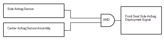
(1) The side airbags are deployed based on signals from the side airbag sensors and center airbag sensor assembly.
HINT:
The curtain shield airbags and front pretensioners are deployed at the same time.
(c) SIDE COLLISION (2)
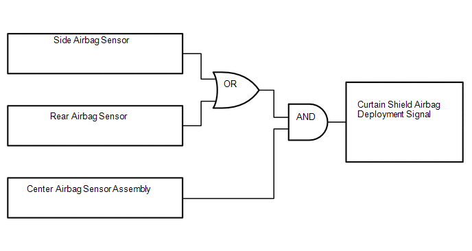
(1) The curtain shield airbags are deployed when both of the following conditions are met:
- Signals from the side airbag sensors or rear airbag sensors are received.
- Signal from the center airbag sensor assembly is received.
 How To Proceed With Troubleshooting
CAUTION / NOTICE / HINT
HINT:
*: Use the Techstream.
PROCEDURE
1.
VEHICLE BROUGHT TO WORKSHOP
NEXT
...
 Problem Symptoms Table
PROBLEM SYMPTOMS TABLE
HINT:
Use the table below to help determine the cause of problem symptoms.
If multiple suspected areas are listed, the potential causes of the symptoms
are lis ...
Other materials about Toyota Venza:
Installation
INSTALLATION
PROCEDURE
1. INSTALL NO. 3 ANTENNA CORD SUB-ASSEMBLY
(a) Pass the washer hose through the No. 3 antenna cord sub-assembly.
(b) Pass the No. 3 antenna cord sub-assembly with washer hose through
the vehicle body as shown in the il ...
Inspection
INSPECTION
CAUTION / NOTICE / HINT
NOTICE:
Ensure that fingers or articles of clothing do not get caught in moving parts
when performing this test.
PROCEDURE
1. INSPECT WINDSHIELD WIPER MOTOR ASSEMBLY
(a) Check the LO operation.
(1) Conne ...
Actuator Check
ACTUATOR CHECK
1. ACTUATOR CHECK
(a) Start the engine and warm it up.
(b) Perform the indicator check (See page
).
(c) Press the "Recirculation/Fresh" switch to perform the actuator check.
HINT:
Be sure to perform the actuator check after ...

0.1359