Toyota Venza: Components
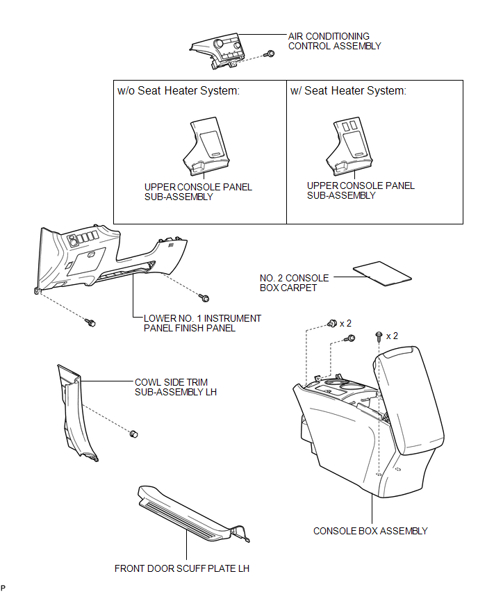
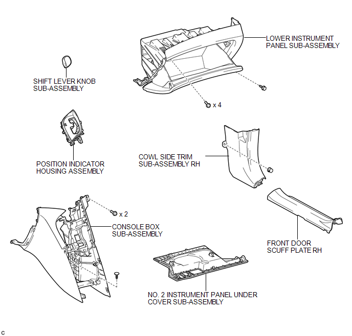
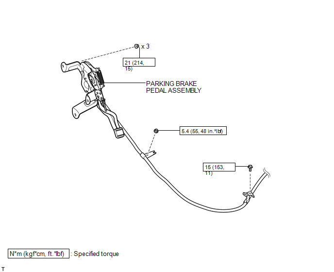
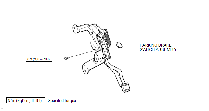
COMPONENTS
ILLUSTRATION
ILLUSTRATION
ILLUSTRATION
ILLUSTRATION

 Removal
REMOVAL
PROCEDURE
1. DISCONNECT CABLE FROM NEGATIVE BATTERY TERMINAL
CAUTION:
Wait at least 90 seconds after disconnecting the cable from the negative (-)
battery terminal to disable the SRS sys ...
Other materials about Toyota Venza:
Installation
INSTALLATION
PROCEDURE
1. INSTALL REAR DOOR BELT MOULDING
(a) Engage the 5 claws to install the rear door belt moulding.
2. INSTALL REAR DOOR GLASS SUB-ASSEMBLY
3. INSTALL REAR DOOR WINDOW DIVIS ...
Poor Sound Quality in All Modes (Low Volume)
PROCEDURE
1.
CHECK AUDIO SETTINGS
(a) Set treble, middle and bass to the initial values and check that the sound
is normal.
OK:
The sound returns to normal.
HINT:
Sound quality adjustment measures vary according to the ...
Inspection
INSPECTION
PROCEDURE
1. INSPECT UNIVERSAL JOINT SPIDER ASSEMBLY
(a) Check the spider bearing axial play by turning the flange while holding
the shaft tightly.
HINT:
If necessary, replace the propeller with center bearing shaft assembly. ...

0.1635