Toyota Venza: Components
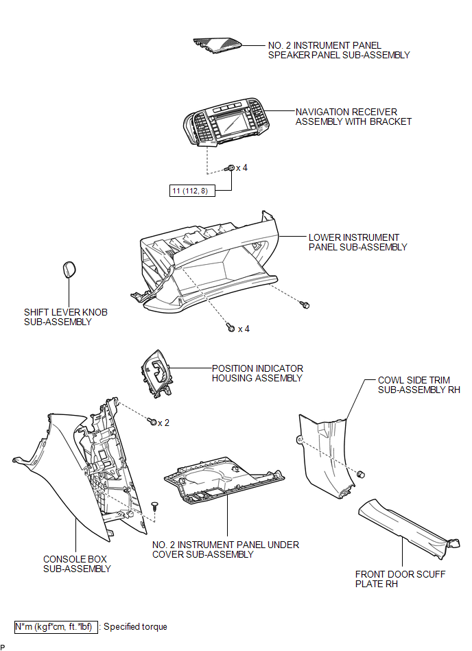
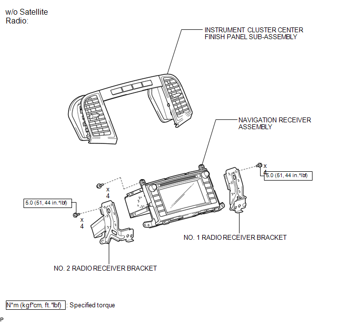
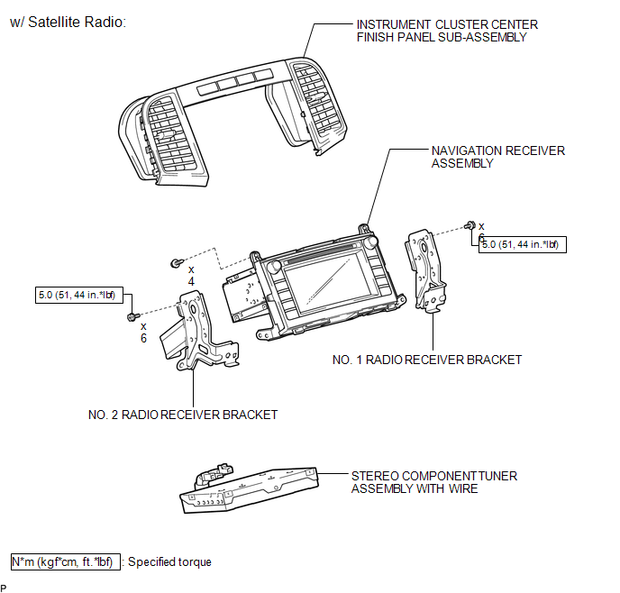
COMPONENTS
ILLUSTRATION
.png)
ILLUSTRATION
ILLUSTRATION
ILLUSTRATION

 Removal
REMOVAL
PROCEDURE
1. PRECAUTION
(See page )
NOTICE:
After turning the ignition switch off, waiting time may be required before disconnecting
the cable from the negative (-) battery terminal. T ...
Other materials about Toyota Venza:
Installation
INSTALLATION
PROCEDURE
1. INSTALL ECM
(a) Install the bracket to the ECM with the 5 screws.
(b) Install the ECM with the 3 bolts.
Torque:
8.0 N·m {82 kgf·cm, 71 in·lbf}
...
Screen Flicker or Color Distortion
PROCEDURE
1.
CHECK DISPLAY SETTING
(a) Reset display settings (contrast, brightness) and check that the screen appears
normal.
OK:
The display returns to normal.
OK
END
NG
...
Power Mirror Control System(w/o Memory)
Parts Location
PARTS LOCATION
ILLUSTRATION
Problem Symptoms Table
PROBLEM SYMPTOMS TABLE
HINT:
Use the table below to help determine the cause of problem symptoms. If multiple
suspected areas are listed, the potential causes of the symptoms are l ...

0.1303