Toyota Venza: Components
COMPONENTS
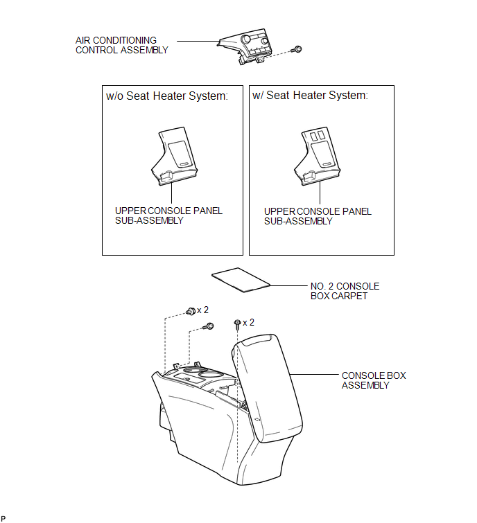
ILLUSTRATION
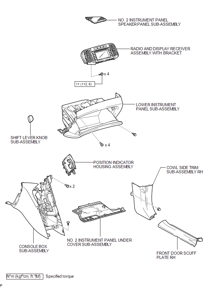
ILLUSTRATION
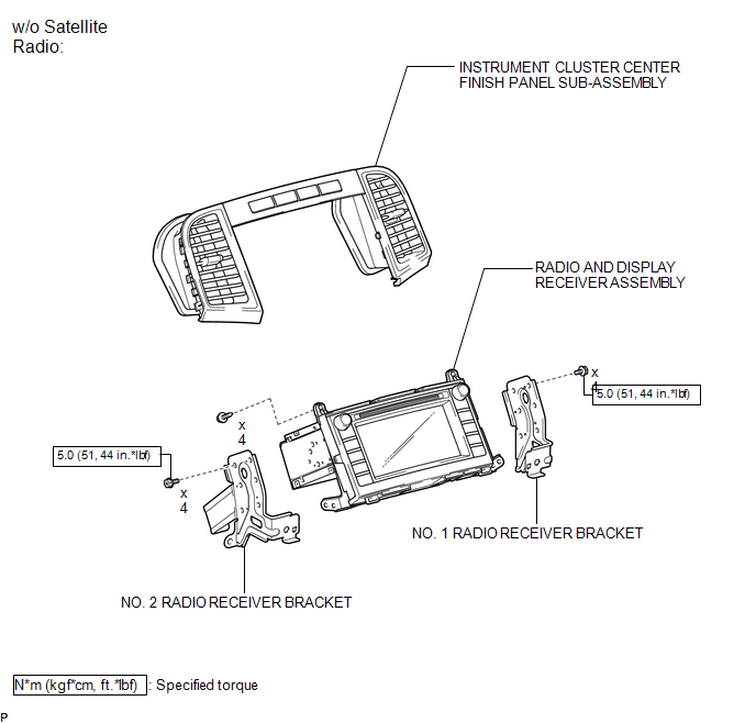
ILLUSTRATION
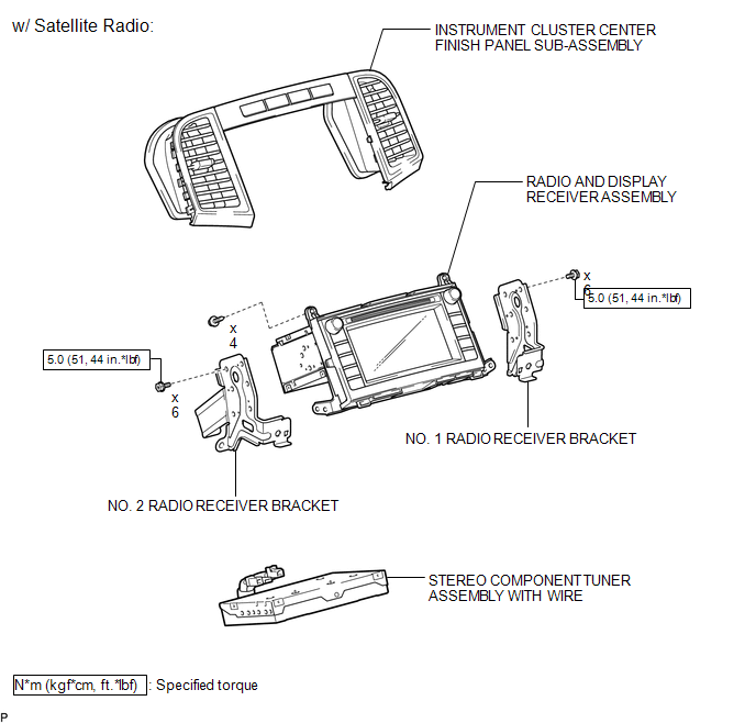
ILLUSTRATION
 Radio Receiver
...
 Removal
REMOVAL
PROCEDURE
1. REMOVE UPPER CONSOLE PANEL SUB-ASSEMBLY (w/o Seat Heater System)
2. REMOVE UPPER CONSOLE PANEL SUB-ASSEMBLY (w/ Seat Heater System)
3. REMOVE NO. 2 CONSOLE BOX CARPET
...
Other materials about Toyota Venza:
Transmitter ID not Registered (C2171/71)
DESCRIPTION
Each tire pressure warning valve and transmitter ID is registered to the tire
pressure warning ECU.
When the ECU detects a transmitter ID code not registered in the ECU, a DTC is
output.
DTC No.
DTC Detection Condition
...
Installation
INSTALLATION
PROCEDURE
1. INSTALL FUEL PRESSURE REGULATOR ASSEMBLY
(a) Apply a light coat of gasoline to 2 new O-rings, and install them
onto the fuel pressure regulator.
Text in Illustration
*1
New O-r ...
Inspection
INSPECTION
PROCEDURE
1. INSPECT DRIVER SIDE LUMBAR SWITCH
(a) Measure the resistance between the terminals when the switch is operated.
Standard Resistance:
Tester Connection
Switch Condition
...

0.1121