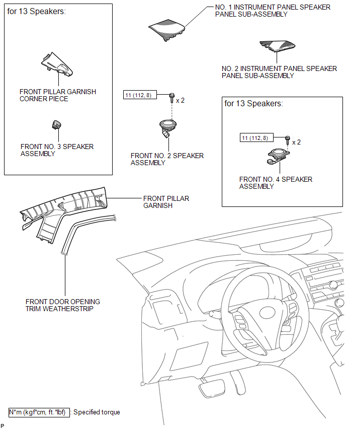
Toyota Venza: Components
COMPONENTS
ILLUSTRATION

 Removal
REMOVAL
PROCEDURE
1. DISCONNECT FRONT DOOR OPENING TRIM WEATHERSTRIP
2. REMOVE FRONT PILLAR GARNISH
3. REMOVE NO. 2 INSTRUMENT PANEL SPEAKER PANEL SUB-ASSEMBLY
4. REMOVE FRONT NO. 4 SPEA ...
Other materials about Toyota Venza:
Throttle Actuator Control Motor Circuit Low (P2102,P2103)
DESCRIPTION
The throttle actuator is operated by the ECM and opens and closes the throttle
valve using gears.
The opening angle of the throttle valve is detected by the throttle position
sensor, which is mounted on the throttle body. The throttle positio ...
Removal
REMOVAL
PROCEDURE
1. REMOVE FRONT WIPER ARM HEAD CAP
2. REMOVE FRONT WIPER ARM AND BLADE ASSEMBLY LH
3. REMOVE FRONT WIPER ARM AND BLADE ASSEMBLY RH
4. REMOVE FRONT FENDER TO COWL SIDE SEAL LH
5. REMOVE FRONT FENDER TO COWL SIDE SEAL RH
6 ...
Installation
INSTALLATION
PROCEDURE
1. INSTALL POWER OUTLET SOCKET COVER NO.1
(a) Engage the 2 claws to install the power point socket cover.
2. INSTALL POWER POINT SOCKET ASSEMBLY
(a) Engage the 2 c ...

0.1325