Toyota Venza: Inspection
INSPECTION
PROCEDURE
1. INSPECT CYLINDER HEAD SUB-ASSEMBLY
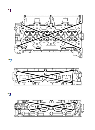
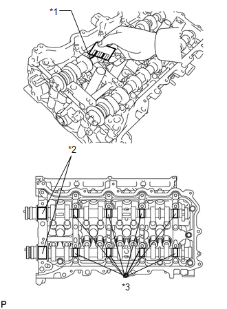
(a) Using a precision straightedge and feeler gauge, measure the warpage of the contact surfaces where the cylinder head contacts the cylinder block and manifold.
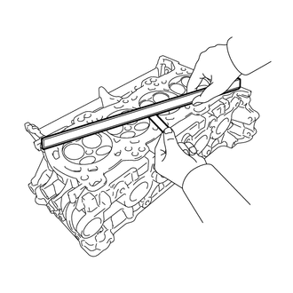
Maximum Warpage:
|
Item |
Specified Condition |
|---|---|
|
Cylinder head lower side |
0.05 mm (0.00197 in.) |
|
Intake manifold side |
0.10 mm (0.00394 in.) |
|
Exhaust manifold side |
0.10 mm (0.00394 in.) |
If the warpage is more than the maximum, replace the cylinder head.
Text in Illustration|
*1 |
Cylinder Head Lower Side: |
|
*2 |
Intake Manifold Side: |
|
*3 |
Exhaust Manifold Side: |
|
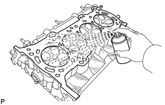
(b) Using a dye penetrant, check the intake ports, exhaust ports and cylinder surface for cracks. If cracked, replace the cylinder head. |
|
2. INSPECT COMPRESSION SPRING
|
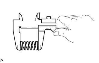
(a) Using a vernier caliper, measure the free length of the inner compression spring. Standard free length: 50.0 mm (1.97 in.) If the free length is not as specified, replace the spring. |
|
|
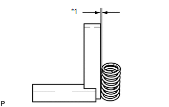
(b) Using a steel square, measure the deviation of the inner compression spring. Text in Illustration
Maximum deviation: 1.0 mm (0.0394 in.) Maximum angle: 2° If the deviation is more than the maximum, replace the spring. |
|
3. INSPECT INTAKE VALVE
|
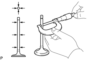
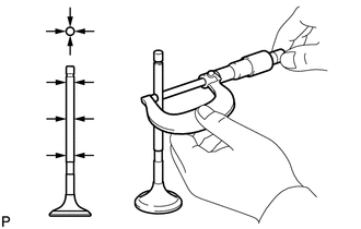
(a) Using a micrometer, measure the diameter of the valve stem. Standard valve stem diameter: 5.470 mm to 5.485 mm (0.2154 to 0.2159 in.) |
|
|
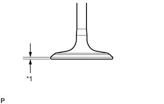
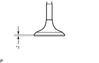
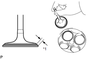
(b) Using a vernier caliper, measure the valve head margin thickness. Text in Illustration
Standard margin thickness: 1.0 mm (0.0394 in.) Minimum margin thickness: 0.50 mm (0.0197 in.) If the margin thickness is less than the minimum, replace the valve. |
|
|
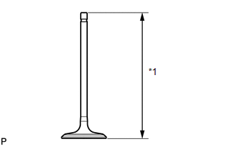
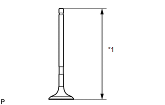
(c) Using a vernier caliper, measure the overall length of the valve. Text in Illustration
Standard overall length: 103.92 mm (4.09 in.) Minimum overall length: 103.42 mm (4.07 in.) If the overall length is less than the minimum, replace the intake valve. |
|
4. INSPECT EXHAUST VALVE
|
(a) Using a micrometer, measure the diameter of the valve stem. Standard valve stem diameter: 5.465 mm to 5.480 mm (0.2152 to 0.2157 in.) |
|
|
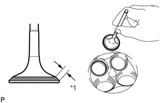
(b) Using a vernier caliper, measure the valve head margin thickness. Text in Illustration
Standard margin thickness: 1.0 mm (0.0394 in.) Minimum margin thickness: 0.50 mm (0.0197 in.) If the margin thickness is less than the minimum, replace the exhaust valve. |
|
|
(c) Using a vernier caliper, measure the overall length of the valve. Text in Illustration
Standard overall length: 112.91 mm (4.44 in.) Minimum overall length: 112.41 mm (4.43 in.) If the overall length is less than the minimum, replace the exhaust valve. |
|
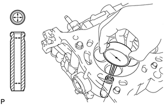
5. INSPECT VALVE GUIDE BUSH OIL CLEARANCE
|
(a) Using a caliper gauge, measure the inside diameter of the guide bush. Standard bush inside diameter: 5.510 to 5.530 mm (0.2169 to 0.2177 in.) |
|
(b) Subtract the valve stem diameter measurement from the guide bush inside diameter measurement.
Standard Oil Clearance:
|
Item |
Specified Condition |
|---|---|
|
Intake |
0.025 to 0.060 mm (0.000984 to 0.00236 in.) |
|
Exhaust |
0.030 to 0.065 mm (0.00118 to 0.00256 in.) |
Maximum Oil Clearance:
|
Item |
Specified Condition |
|---|---|
|
Intake |
0.08 mm (0.00315 in.) |
|
Exhaust |
0.10 mm (0.00394 in.) |
If the oil clearance is more than the maximum, replace the valve and guide bush.
6. INSPECT INTAKE VALVE SEAT
(a) Apply a light coat of Prussian blue to the valve face.
|
(b) Lightly press the valve face against the valve seat. Text in Illustration
HINT: Do not rotate the valve while pressing the valve. |
|
(c) Check the valve face and valve seat.
(1) Check that the contact surfaces of the valve seat and valve face are in the middle area of their respective surfaces, with the width between 1.1 and 1.5 mm (0.0433 and 0.0591 in.).
If not, correct the valve seat.
(2) Check that the contact surfaces of the valve seat and valve face are even around the entire valve seat.
If not, correct the valve seat.
7. INSPECT EXHAUST VALVE SEAT
(a) Apply a light coat of Prussian blue to the valve face.
|
(b) Lightly press the valve face against the valve seat. Text in Illustration
HINT: Do not rotate the valve while pressing the valve. |
|
(c) Check the valve face and valve seat.
(1) Check that the contact surfaces of the valve seat and valve face are in the middle area of their respective surfaces, with the width between 1.1 and 1.5 mm (0.0433 and 0.0591 in.).
If not, correct the valve seat.
(2) Check that the contact surfaces of the valve seat and valve face are even around the entire valve seat.
If not, correct the valve seat.
8. INSPECT CAMSHAFT OIL CLEARANCE
NOTICE:
Do not turn the camshafts.
(a) Clean the bearing caps, camshaft housing and camshaft journals.
(b) Place the camshafts on the camshaft housing.
|
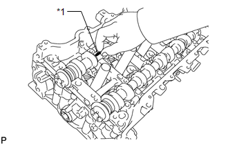
(c) Lay a strip of Plastigage across each of the camshaft journals. Text in Illustration
|
|
(d) Install the camshaft bearing caps (See page
.gif) ).
).
(e) Install the camshaft housing sub-assembly (See page
).
(f) Remove the camshaft bearing caps (See page
).
|
(g) Measure the Plastigage at its widest point. Standard Oil Clearance:
Maximum Oil Clearance:
If the oil clearance is more than the maximum, replace the camshaft. If necessary, replace the camshaft housing. Text in Illustration
|
|
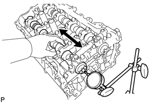
9. INSPECT CAMSHAFT THRUST CLEARANCE
(a) Inspect the intake camshaft.
(1) Install the intake camshaft.
|
(2) Using a dial indicator, measure the thrust clearance while moving the camshaft back and forth. If the thrust clearance is more than the maximum, replace the camshaft housing. If the thrust surface is damaged, replace the camshaft. |
|
(b) Inspect the intake and exhaust camshafts.
(1) Install the intake and exhaust camshafts.
(2) Using a dial indicator, measure the thrust clearance while moving the camshaft back and forth.
Standard thrust clearance:
0.060 to 0.155 mm (0.00236 to 0.00610 in.)
Maximum thrust clearance:
0.170 mm (0.00669 in.)
If the thrust clearance is more than the maximum, replace the camshaft housing. If the thrust surface is damaged, replace the camshaft.
 Disassembly
DISASSEMBLY
PROCEDURE
1. REMOVE INTAKE VALVE
(a) Using SST and wooden blocks, compress the compression spring and
remove the valve spring retainer locks.
SST: 09202-70020
09202 ...
 Replacement
REPLACEMENT
PROCEDURE
1. REPLACE INTAKE VALVE GUIDE BUSH
(a) Heat the cylinder head to approximately 80 to 100°C (176 to 212°F).
(b) Place the cylinder head on wooden blocks.
(c) Usi ...
Other materials about Toyota Venza:
Inspection
INSPECTION
PROCEDURE
1. INSPECT GENERATOR PULLEY WITH CLUTCH
(a) Hold the center of the pulley, and confirm that the outer ring turns
counterclockwise and does not turn clockwise.
Text in Illustration
*1
...
Replacing a flat tire
Chock the tires.
Slightly loosen the wheel nuts (one turn).
Turn the tire jack portion “A” by hand until the notch of the jack is in contact
with the jack point.
Raise the vehicle until the tire is slightly raised off the ground.
Remove a ...
Speed Signal Circuit
DESCRIPTION
The headlight leveling ECU assembly receives the vehicle speed signal from the
combination meter assembly.
HINT:
A voltage of 12 V or 5 V is output from each ECU and then input to the
combination meter. The signal is changed to a p ...

0.131