Toyota Venza: Disassembly
DISASSEMBLY
PROCEDURE
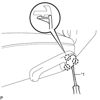
1. REMOVE SEAT ADJUSTER COVER CAP LH
|
(a) Using a screwdriver wrapped with protective tape, disengage the 3 claws and remove the seat adjuster cover cap LH. Text in Illustration
|
|
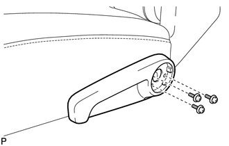
2. REMOVE REAR SEAT RECLINING RELEASE LEVER LH
|
(a) Remove the 3 screws and the rear seat reclining release lever LH. |
|
3. REMOVE REAR SEAT RECLINING COVER LH
|
(a) Remove the 2 screws. |
|
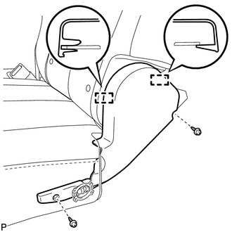
(b) Disengage the 2 guides and remove the rear seat reclining cover LH.
4. REMOVE REAR SEAT INNER RECLINING COVER LH
|
(a) Remove the 2 screws. |
|
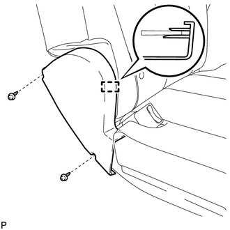
(b) Disengage the guide and remove the rear seat inner reclining cover LH.
5. REMOVE REAR SEAT CUSHION COVER WITH PAD
|
(a) Disengage the 3 hooks. |
|
(b) Disengage each hook and remove the rear seat cushion cover with pad.
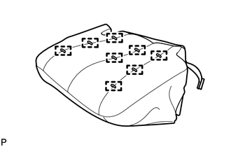
6. REMOVE SEPARATE TYPE REAR SEAT CUSHION COVER
|
(a) Disengage the 8 hog rings and remove the separate type rear seat cushion cover. |
|
7. REMOVE REAR SEAT INNER BELT ASSEMBLY LH
.gif)
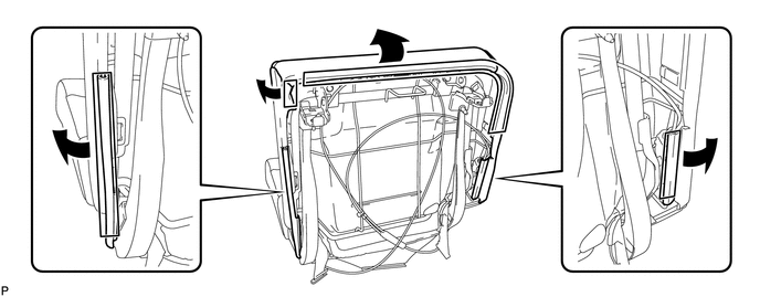
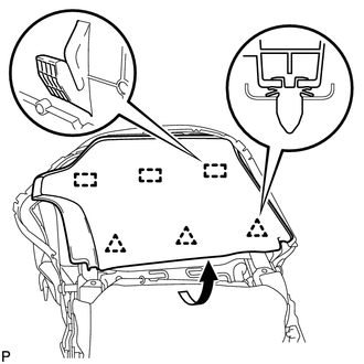
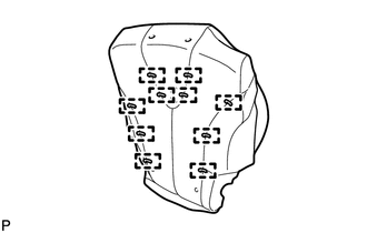
8. REMOVE REAR SEATBACK BOARD LH
|
(a) Disengage the 17 claws. |
|
|
(b) Disengage the 3 clips and 3 guides, and remove the rear seatback board LH as shown in the illustration. |
|
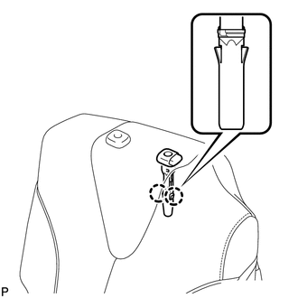
9. REMOVE REAR SEAT HEADREST SUPPORT LH
|
(a) Disengage the 2 claws and remove the rear seat headrest support LH. |
|
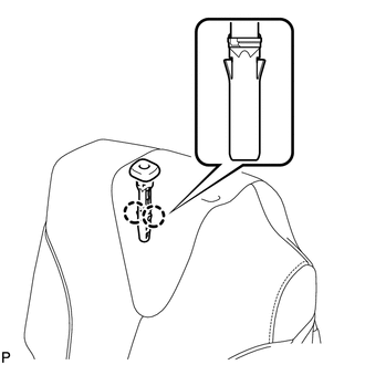
10. REMOVE REAR SEAT HEADREST SUPPORT RH
|
(a) Disengage the 2 claws and remove the rear seat headrest support RH. |
|
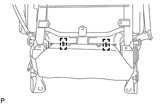
11. REMOVE REAR SEATBACK COVER WITH PAD
|
(a) Disengage the 2 hog rings and remove the rear seatback cover with pad. |
|
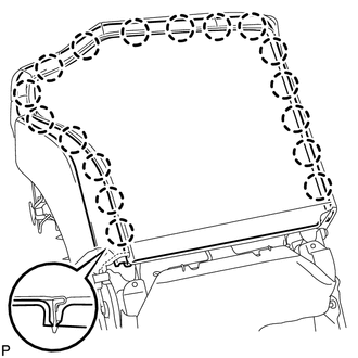
12. REMOVE SEPARATE TYPE REAR SEATBACK COVER
|
(a) Disengage the 10 hog rings and remove the separate type rear seatback cover. |
|
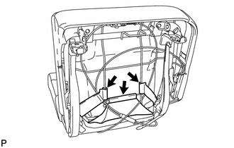
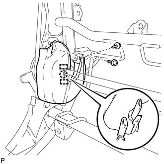
13. REMOVE REAR SEAT NO. 2 RECLINING CONTROL CABLE SUB-ASSEMBLY
|
(a) Disengage the 4 control cable clamps and claw as shown in the illustration. |
|
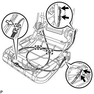
(b) Remove the 2 clamps and the rear seat No. 2 reclining control cable sub-assembly.
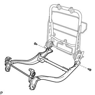
14. REMOVE REAR SEAT CUSHION FRAME SUB-ASSEMBLY LH
|
(a) Remove the 2 bolts. |
|
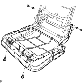
(b) Using a T45 "TORX" socket, remove the 2 "TORX" bolts, 2 bushes and the rear seat cushion frame sub-assembly LH.
15. REMOVE RECLINING ADJUSTER INSIDE COVER LH
|
(a) Remove the 2 screws. |
|
(b) Disengage the claw and 2 guides, and remove the reclining adjuster inside cover LH.
16. REMOVE REAR SEAT LEG SIDE COVER LH
|
(a) Remove the screw. |
|
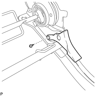
(b) Remove the rear seat leg side cover LH.
17. REMOVE RECLINING ADJUSTER INSIDE COVER RH
|
(a) Remove the 2 screws. |
|
(b) Disengage the claw and 2 guides and remove the reclining adjuster inside cover RH.
18. REMOVE REAR SEAT LEG SIDE COVER
|
(a) Remove the screw. |
|
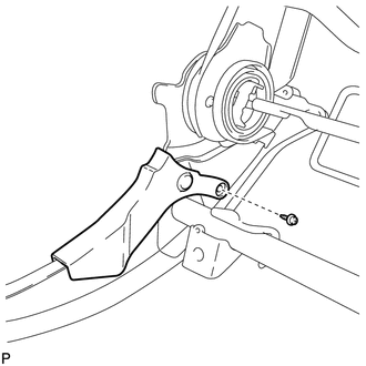
(b) Remove the rear seat leg side cover.
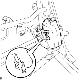
19. REMOVE NO. 1 SEAT LEG ASSEMBLY LH
|
(a) Using a T55 "TORX" socket, remove the 4 "TORX" bolts and the No. 1 seat leg assembly LH. |
|
 Removal
REMOVAL
PROCEDURE
1. REMOVE REAR SEAT HEADREST ASSEMBLY
(a) Press the headrest support button and pull up the headrest as shown
in the illustration to remove it.
...
 Installation
INSTALLATION
PROCEDURE
1. INSTALL REAR SEAT ASSEMBLY LH
(a) Place the rear seat assembly LH in the cabin.
NOTICE:
Be careful not to damage the vehicle body.
(b) Temporarily install th ...
Other materials about Toyota Venza:
Actuator Check
ACTUATOR CHECK
1. ACTUATOR CHECK
(a) Start the engine and warm it up.
(b) Perform the indicator check (See page
).
(c) Press the "Recirculation/Fresh" switch to perform the actuator check.
HINT:
Be sure to perform the actuator check after ...
Main Body Ecu
Components
COMPONENTS
ILLUSTRATION
Removal
REMOVAL
PROCEDURE
1. REMOVE UPPER INSTRUMENT PANEL
HINT:
Refer to the procedure up to Remove Upper Instrument Panel Sub-assembly (See
page ).
2. REMOVE MAIN BODY ECU (DRIVER SIDE JUNCTION BLOCK ASSEM ...
Removal
REMOVAL
CAUTION / NOTICE / HINT
NOTICE:
Do not replace the spiral cable with the battery connected and the ignition
switch ON.
Do not rotate the spiral cable without the steering wheel with the battery
connected and the ignition switch O ...

0.1141