Toyota Venza: Removal
REMOVAL
PROCEDURE
1. REMOVE AIR CONDITIONING UNIT ASSEMBLY
(See page .gif) )
)
2. REMOVE NO. 1 FINISH PANEL MOUNTING BRACKET
3. REMOVE NO. 2 FINISH PANEL MOUNTING BRACKET
4. REMOVE NO. 3 AIR DUCT SUB-ASSEMBLY
5. REMOVE NO. 2 AIR DUCT SUB-ASSEMBLY
6. REMOVE AIR CONDITIONING HARNESS ASSEMBLY
7. REMOVE COOLER EXPANSION VALVE
8. REMOVE BLOWER ASSEMBLY WITH COOLER EVAPORATOR SUB-ASSEMBLY
|
(a) Remove the 6 screws. |
|
.png)
|
(b) Disengage the guide and disconnect the wire harness. |
|
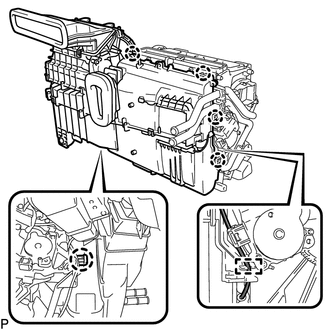
(c) Disengage the 5 claws and remove the blower assembly with cooler evaporator sub-assembly from the air conditioning radiator assembly.
9. REMOVE COOLER EVAPORATOR SUB-ASSEMBLY
10. REMOVE NO. 1 COOLER THERMISTOR
 Components
COMPONENTS
ILLUSTRATION
ILLUSTRATION
ILLUSTRATION
...
 Disassembly
DISASSEMBLY
PROCEDURE
1. REMOVE NO. 1 AIR DUCT SUB-ASSEMBLY
(a) Disengage the 4 claws and remove the No. 1 air duct sub-assembly.
2. REMOV ...
Other materials about Toyota Venza:
Lost Communication with ECM / PCM "A" (U0100,U0129)
DESCRIPTION
The power steering ECU receives signals from the ECM and the brake actuator assembly
(skid control ECU) via the CAN communication system.
DTC No.
DTC Detection Condition
Trouble Area
U0100
...
Installation
INSTALLATION
PROCEDURE
1. INSTALL PARKING BRAKE PEDAL ASSEMBLY
(a) Install the parking brake pedal assembly with the 3 nuts.
Torque:
21 N·m {214 kgf·cm, 15 ft·lbf}
(b) Connect t ...
Rear Wheel House Plate
Components
COMPONENTS
ILLUSTRATION
Installation
INSTALLATION
PROCEDURE
1. INSTALL NO. 2 ROCKER PANEL MOULDING PROTECTOR
(a) Install the No. 2 rocker panel moulding protector with the 2 screws
<B>.
...

0.1329