Toyota Venza: Components
COMPONENTS
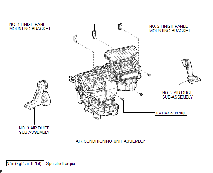
ILLUSTRATION
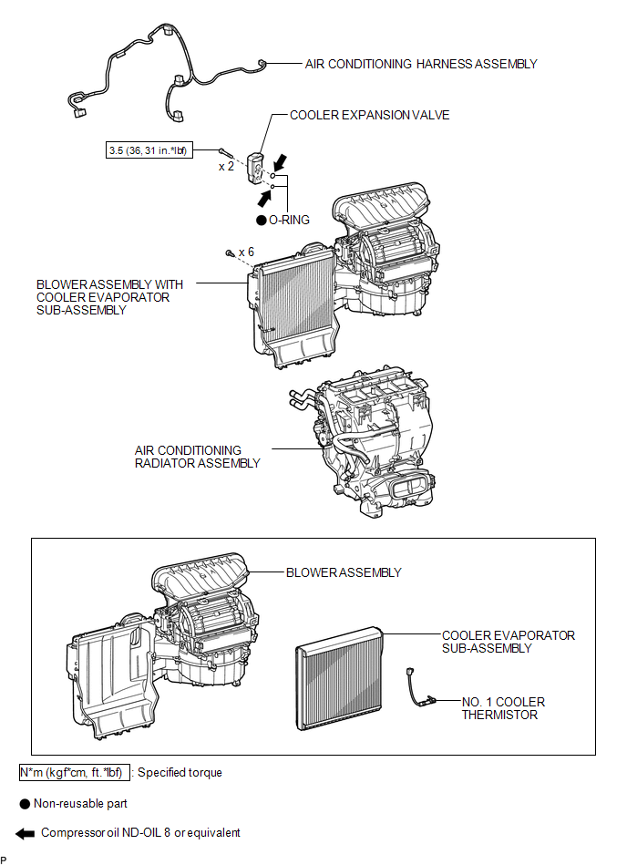
ILLUSTRATION
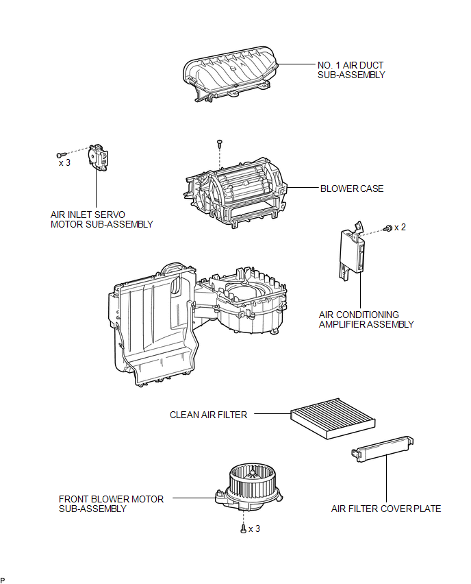
ILLUSTRATION
 Blower Unit
...
 Removal
REMOVAL
PROCEDURE
1. REMOVE AIR CONDITIONING UNIT ASSEMBLY
(See page )
2. REMOVE NO. 1 FINISH PANEL MOUNTING BRACKET
3. REMOVE NO. 2 FINISH PANEL MOUNTING BRACKET
4. REMOVE NO. 3 AIR DUCT ...
Other materials about Toyota Venza:
Torque Sensor Circuit Malfunction (C1511-C1514,C1517)
DESCRIPTION
The torque sensor converts the rotation torque input to the steering wheel into
an electrical signal and sends it to the power steering ECU. Based on this signal,
the ECU detects steering effort.
DTC No.
DTC Detection Co ...
Diagnostic Trouble Code Chart
DIAGNOSTIC TROUBLE CODE CHART
If a trouble code is displayed during the DTC check, check the trouble areas
listed for that code in the table below and proceed to the appropriate page.
Cruise Control System
DTC Code
Detection Item
...
Precaution
PRECAUTION
NOTICE:
When disconnecting the cable from the negative (-) battery terminal, initialize
the following systems after the cable is reconnected.
System Name
See Procedure
Back Door Closer System
...

0.1216