Toyota Venza: Removal
REMOVAL
PROCEDURE
1. DISCONNECT CABLE FROM NEGATIVE BATTERY TERMINAL
NOTICE:
When disconnecting the cable, some systems need to be initialized after the cable
is reconnected (See page .gif) ).
).
2. REMOVE REAR DOOR INSIDE HANDLE BEZEL PLUG
3. REMOVE REAR POWER WINDOW REGULATOR SWITCH ASSEMBLY WITH REAR DOOR ARMREST BASE PANEL
4. REMOVE REAR DOOR TRIM BOARD SUB-ASSEMBLY
5. REMOVE REAR DOOR INSIDE HANDLE SUB-ASSEMBLY
6. REMOVE REAR DOOR SERVICE HOLE COVER
7. REMOVE REAR DOOR CHECK ASSEMBLY
8. REMOVE REAR DOOR WEATHERSTRIP
9. REMOVE REAR DOOR GLASS RUN
10. REMOVE REAR DOOR WINDOW DIVISION BAR SUB-ASSEMBLY
11. REMOVE REAR DOOR GLASS SUB-ASSEMBLY
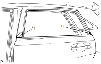
12. REMOVE REAR DOOR BELT MOULDING
|
(a) Put protective tape around the rear door belt moulding. Text in Illustration
|
|
|
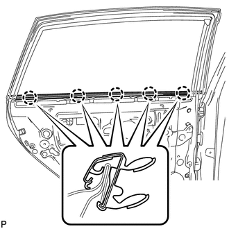
(b) Using a screwdriver, disengage the 5 claws and remove the rear door belt moulding. |
|
 Components
COMPONENTS
ILLUSTRATION
ILLUSTRATION
...
 Installation
INSTALLATION
PROCEDURE
1. INSTALL REAR DOOR BELT MOULDING
(a) Engage the 5 claws to install the rear door belt moulding.
2. INSTALL REAR D ...
Other materials about Toyota Venza:
Terminals Of Ecu
TERMINALS OF ECU
1. CHECK OUTER MIRROR CONTROL ECU ASSEMBLY (DRIVER DOOR)
(a) Disconnect the I13 connector.
(b) Measure the voltage and resistance according to the value(s) in the table
below.
HINT:
Measure the values on the wire harness side with the ...
Front Left Sensor Malfunction (C1AE1)
DESCRIPTION
The No. 1 ultrasonic sensor (front left sensor) is installed on the front bumper.
The ECU detects obstacles based on signals received from the No. 1 ultrasonic sensor
(front left sensor). If the No. 1 ultrasonic sensor (front left sensor) has ...
Removal
REMOVAL
PROCEDURE
1. PRECAUTION
CAUTION:
Be sure to read Precaution thoroughly before servicing (See page
).
If the front seat side airbag assembly was deployed, replace the front
seat side airbag assembly, front seat frame assembly wit ...

0.1328