Toyota Venza: Components
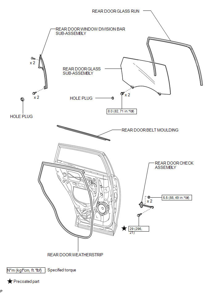
COMPONENTS
ILLUSTRATION
.png)
ILLUSTRATION

 Removal
REMOVAL
PROCEDURE
1. DISCONNECT CABLE FROM NEGATIVE BATTERY TERMINAL
NOTICE:
When disconnecting the cable, some systems need to be initialized after the cable
is reconnected (See page ).
2. RE ...
Other materials about Toyota Venza:
Voice is not Recognized
PROCEDURE
1.
CHECK CONDITION
(a) Check if the system voice recognition level is low when recognizing a particular
voice.
Result
Proceed to
System voice recognition level is low only fo ...
Wireless Transmitter Memory Function does not Operate
DESCRIPTION
With the ignition switch off and the driver door closed, pressing the manual
lock or unlock switch on the power window regulator master switch assembly while
holding a seat memory switch (M1 switch or M2 switch) will register the transmitter
...
Diagnosis System
DIAGNOSIS SYSTEM
1. CHECK DLC3
(a) Check the DLC3 (See page ).
2. FUNCTION OF P/S WARNING LIGHT
(a) When a malfunction is detected in the power steering system, the P/S warning
light on the accessory meter comes on to inform the driver of the malfunctio ...

0.18