Toyota Venza: Check Mode Procedure
CHECK MODE PROCEDURE
1. DESCRIPTION
(a) Check mode has a higher sensitivity to malfunctions and can detect malfunctions that normal mode cannot detect. Check mode can also detect all the malfunctions that normal mode can detect. In check mode, DTCs are detected with 1 trip detection logic.
2. CHECK MODE PROCEDURE
(a) Make sure that the following conditions are met:
(1) Battery positive voltage 11 V or more.
(2) Throttle valve fully closed.
(3) Shift lever in P or N.
(4) A/C off.
(b) Turn the ignition switch off.
(c) Connect the Techstream to the DLC3.
(d) Turn the ignition switch to ON.
(e) Turn the Techstream on.
(f) Enter the following menus: Powertrain / ECT / Check Mode.
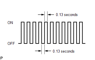
(g) Change the TCM to check mode. Make sure the MIL flashes as shown in the illustration.
NOTICE:
All DTCs and freeze frame data will be cleared if: 1) the Techstream is used to change the TCM from normal mode to check mode or vice versa; or 2) during check mode, the ignition switch is turned from ON to ACC or off.
Before entering check mode, make notes of the DTCs and freeze frame data.
(h) Start the engine. The MIL should turn off after the engine starts.
(i) Perform Monitor Drive Pattern for the ECT test (See page
.gif) ).
).
(Or, simulate the conditions of the malfunction described by the customer.)
(j) After simulating the malfunction conditions, use the Techstream to check the DTC and freeze frame data.
 Dtc Check / Clear
DTC CHECK / CLEAR
NOTICE:
When the diagnosis system is changed from normal mode to check mode or vice versa,
all DTCs and freeze frame data recorded in normal mode are cleared. Before changing
m ...
 Fail-safe Chart
FAIL-SAFE CHART
1. Fail-safe
This function minimizes the loss of operation when any abnormality occurs in
a sensor or solenoid.
Fail-safe Control List
Malfunction Part
Func ...
Other materials about Toyota Venza:
Transmitter ID not Received in Main Mode (C2126/26)
DESCRIPTION
After all IDs are registered, DTC C2126/26 is set in the tire pressure warning
ECU and the tire pressure warning light blinks for 1 minute and then comes on.
When the tire pressure warning ECU successfully receives radio waves from all
the tr ...
Knock Sensor
Components
COMPONENTS
ILLUSTRATION
Removal
REMOVAL
PROCEDURE
1. REMOVE INTAKE MANIFOLD
(a) Remove the intake manifold (See page ).
2. REMOVE KNOCK SENSOR
(a) Disconnect the sensor connector.
...
Entire Combination Meter does not Operate
DESCRIPTION
This circuit is the power source circuit for the meter. This circuit provides
two types of power sources; one is a constant power source mainly used as a backup
power source, and the other is an IG power source mainly used for signal transmiss ...

0.1282