Toyota Venza: Data Signal Circuit between Navigation Receiver Assembly and Extension Module
DESCRIPTION
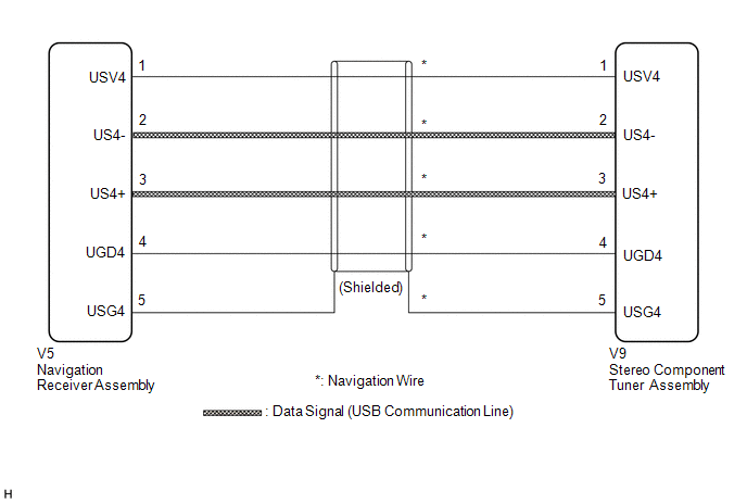
The stereo component tuner assembly sends the image data signal to the navigation receiver assembly via this circuit.
WIRING DIAGRAM
PROCEDURE
|
1. |
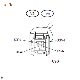
CHECK NAVIGATION WIRE |
(a) Remove the navigation wire (See page .gif) ).
).
|
(b) Measure the resistance according to the value(s) in the table below. Standard Resistance:
|
|
| OK | .gif) |
PROCEED TO NEXT SUSPECTED AREA SHOWN IN PROBLEM SYMPTOMS TABLE |
| NG | |
REPLACE NAVIGATION WIRE |
 Sound Signal Circuit between Navigation Receiver Assembly and Stereo Jack Adapter
DESCRIPTION
The No. 1 stereo jack adapter assembly sends the sound signal from an external
device to the navigation receiver assembly via this circuit.
The sound signal that has been sent is ampli ...
 Data Signal Circuit between Navigation Receiver Assembly and Stereo Jack Adapter
DESCRIPTION
The No. 1 stereo jack adapter assembly sends the sound data signal or image data
signal from a USB device to the navigation receiver assembly via this circuit.
WIRING DIAGRAM
PROCED ...
Other materials about Toyota Venza:
Diagnosis System
DIAGNOSIS SYSTEM
1. DESCRIPTION
When troubleshooting OBD II (On-Board Diagnostics) vehicles, an OBD
II scan tool (complying with SAE J1987) must be connected to the DLC3 (Data
Link Connector 3) of the vehicle. Various data in the vehicle ECM ( ...
Components
COMPONENTS
ILLUSTRATION
ILLUSTRATION
ILLUSTRATION
ILLUSTRATION
ILLUSTRATION
...
Center Airbag Sensor Assembly Communication Circuit Malfunction (B1790)
DESCRIPTION
The center airbag sensor assembly communication circuit consists of the occupant
classification ECU and center airbag sensor assembly.
DTC B1790 is recorded when a malfunction is detected in the center airbag sensor
assembly communication cir ...

0.1597