Toyota Venza: Installation
INSTALLATION
PROCEDURE
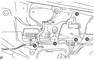
1. INSTALL TELEVISION CAMERA ASSEMBLY (w/ Rear View Monitor System)
.gif)
2. INSTALL BACK DOOR OPENER SWITCH ASSEMBLY
3. INSTALL NO. 1 BACK DOOR EMBLEM
4. INSTALL NO. 2 BACK DOOR NAME PLATE
5. INSTALL BACK DOOR OUTSIDE GARNISH SUB-ASSEMBLY
(a) Install the 5 stud bolts and 5 new gaskets to the back door outside garnish sub-assembly.
(b) Install 16 new clips (back door moulding clip) to the back door outside garnish sub-assembly.
|
(c) Engage the 16 clips to install the back door outside garnish sub-assembly. |
|
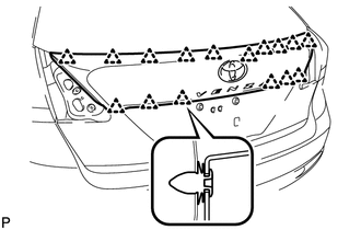
|
(d) Install the 5 nuts. |
|
(e) Connect each connector.
6. INSTALL REAR LIGHT ASSEMBLY LH
7. INSTALL REAR LIGHT ASSEMBLY RH
HINT:
Use the same procedure for the RH side and LH side.
8. INSTALL REAR WIPER MOTOR AND BRACKET ASSEMBLY
9. INSTALL REAR WIPER MOTOR GROMMET
10. INSTALL REAR WIPER ARM AND BLADE ASSEMBLY
11. INSTALL REAR WIPER ARM HEAD CAP
12. INSTALL BACK DOOR PANEL TRIM ASSEMBLY
 Components
COMPONENTS
ILLUSTRATION
ILLUSTRATION
...
 Removal
REMOVAL
PROCEDURE
1. REMOVE BACK DOOR PANEL TRIM ASSEMBLY
2. REMOVE REAR WIPER ARM HEAD CAP
3. REMOVE REAR WIPER ARM AND BLADE ASSEMBLY
4. REMOVE REAR WIPER MOTOR GROMMET
5. REMOVE R ...
Other materials about Toyota Venza:
System Description
SYSTEM DESCRIPTION
1. POWER DOOR LOCK CONTROL SYSTEM DESCRIPTION
(a) The power door lock system locks/unlocks all doors.
The door control switch sends "lock/unlock" request signals to the main body
ECU (driver side junction block assembly). Then ...
Removal
REMOVAL
CAUTION / NOTICE / HINT
HINT:
Use the same procedure for the LH side and RH side.
The following procedure listed is for the LH side.
PROCEDURE
1. REMOVE FRONT WHEEL
2. REMOVE FRONT AXLE SHAFT NUT
3. SEPARATE FRONT SPEED SENS ...
Power Source Control ECU Malfunction (B2782)
DESCRIPTION
The power management control ECU controls the power supply to activate the steering
lock motor. This prevents the steering wheel from being locked while the vehicle
is moving.
DTC No.
DTC Detecting Condition
T ...

0.1231