Toyota Venza: Open in CAN Main Bus Line
DESCRIPTION
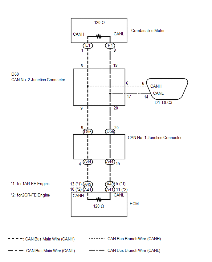
There may be an open circuit in the CAN bus main wire and/or the DLC3 branch wire when the resistance between terminals 6 (CANH) and 14 (CANL) of the DLC3 is 70 Ω or higher.
|
Symptom |
Trouble Area |
|---|---|
|
Resistance between terminals 6 (CANH) and 14 (CANL) of DLC3 is 70 Ω or higher. |
|
WIRING DIAGRAM
CAUTION / NOTICE / HINT
NOTICE:
- Turn the ignition switch off before measuring the resistances between CAN bus main wires and between CAN bus branch wires.
- Turn the ignition switch off before inspecting CAN bus wires for a ground short.
- After the ignition switch is turned off, check that the key reminder warning system and light reminder warning system are not operating.
- Before measuring the resistance, leave the vehicle as is for at least 1 minute and do not operate the ignition switch, any other switches or the doors. If any doors need to be opened in order to check connectors, open the doors and leave them open.
HINT:
- Operating the ignition switch, any other switches or a door triggers related ECU and sensor communication on the CAN. This communication will cause the resistance value to change.
- Even after DTCs are cleared, if a DTC is stored again after driving the vehicle for a while, the malfunction may be occurring due to vibration of the vehicle. In such a case, wiggling the ECUs or wire harness while performing the inspection below may help determine the cause of the malfunction.
PROCEDURE
|
1. |
CHECK FOR OPEN IN CAN BUS WIRE (DLC3 BRANCH WIRE) |
(a) Turn the ignition switch off.
|
(b) Measure the resistance according to the value(s) in the table below. Standard Resistance:
NOTICE: When the measured value is 133 Ω or higher and a CAN communication system
DTC is output, there may be a fault besides disconnection of the DLC3 branch
wire. For that reason, troubleshooting should be performed again from How
to Proceed with Troubleshooting after repairing the trouble area (See page
|
|
.gif) ).
)..png)
| NG | .gif) |
REPAIR OR REPLACE CAN BRANCH WIRE CONNECTED TO DLC3 |
|
.gif)
|
2. |
CHECK FOR OPEN IN CAN BUS WIRE (ECM) |
(a) for 1AR-FE engine:
|
(1) Disconnect the ECM connector (A49). Text in Illustration
|
|
.png)
(2) Measure the resistance according to the value(s) in the table below.
Standard Resistance:
|
Tester Connection |
Switch Condition |
Specified Condition |
|---|---|---|
|
A49-13 (CANH) - A49-5 (CANL) |
Ignition switch off |
108 to 132 Ω |
(b) for 2GR-FE engine:
|
(1) Disconnect the ECM connector (A41). Text in Illustration
|
|
.png)
(2) Measure the resistance according to the value(s) in the table below.
Standard Resistance:
|
Tester Connection |
Switch Condition |
Specified Condition |
|---|---|---|
|
A41-10 (CANH) - A41-11 (CANL) |
Ignition switch off |
108 to 132 Ω |
|
Result |
Proceed to |
|---|---|
|
OK (for 1AR-FE engine) |
A |
|
OK (for 2GR-FE engine) |
B |
|
NG |
C |
| A | |
REPLACE ECM |
| B | |
REPLACE ECM |
|
|
3. |
CHECK FOR OPEN IN CAN BUS WIRE (COMBINATION METER) |
(a) Reconnect the ECM connector.
|
(b) Disconnect the combination meter connector (E1). Text in Illustration
|
|
.png)
(c) Measure the resistance according to the value(s) in the table below.
Standard Resistance:
|
Tester Connection |
Switch Condition |
Specified Condition |
|---|---|---|
|
E1-1 (CANH) - E1-9 (CANL) |
Ignition switch off |
108 to 132 Ω |
| OK | |
REPLACE COMBINATION METER |
|
|
4. |
CHECK FOR OPEN IN CAN BUS WIRE (CAN NO. 1 JUNCTION CONNECTOR - ECM) |
(a) Reconnect the combination meter connector.
|
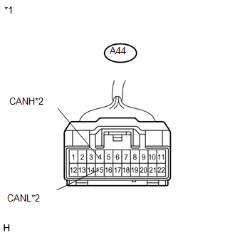
(b) Disconnect the CAN No. 1 junction connector (A44). Text in Illustration
|
|
(c) Measure the resistance according to the value(s) in the table below.
Standard Resistance:
|
Tester Connection |
Switch Condition |
Specified Condition |
|---|---|---|
|
A44-4 (CANH) - A44-15 (CANL) |
Ignition switch off |
108 to 132 Ω |
| NG | |
REPAIR OR REPLACE CAN BUS MAIN WIRE OR CONNECTOR (CAN NO. 1 J/C - ECM) |
|
|
5. |
CHECK FOR OPEN IN CAN BUS WIRE (CAN NO. 1 JUNCTION CONNECTOR - CAN NO. 2 JUNCTION CONNECTOR) |
(a) Reconnect the CAN No. 1 junction connector (A44).
|
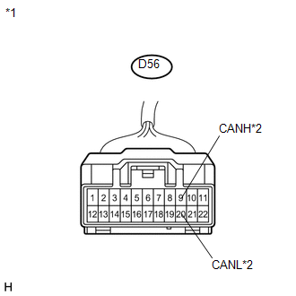
(b) Disconnect the CAN No. 1 junction connector (D56). Text in Illustration
|
|
(c) Measure the resistance according to the value(s) in the table below.
Standard Resistance:
|
Tester Connection |
Switch Condition |
Specified Condition |
|---|---|---|
|
D56-9 (CANH) - D56-20 (CANL) |
Ignition switch off |
108 to 132 Ω |
| OK | |
REPLACE CAN NO. 1 JUNCTION CONNECTOR |
|
|
6. |
CHECK FOR OPEN IN CAN BUS WIRE (CAN NO. 2 JUNCTION CONNECTOR) |
(a) Reconnect the CAN No. 1 junction connector (D56).
|
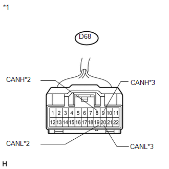
(b) Disconnect the CAN No. 2 junction connector. Text in Illustration
|
|
(c) Measure the resistance according to the value(s) in the table below.
Standard Resistance:
|
Tester Connection |
Switch Condition |
Specified Condition |
Connect to |
|---|---|---|---|
|
D68-8 (CANH) - D68-19 (CANL) |
Ignition switch off |
108 to 132 Ω |
Combination meter |
|
D68-9 (CANH) - D68-20 (CANL) |
Ignition switch off |
108 to 132 Ω |
CAN No. 1 junction connector |
|
Result |
Proceed to |
|---|---|
|
OK |
A |
|
NG (to Combination meter main wire) |
B |
|
NG (to CAN No. 1 junction connector) |
C |
| A | |
REPLACE CAN NO. 2 JUNCTION CONNECTOR |
| B | |
REPAIR OR REPLACE CAN BUS MAIN WIRE OR CONNECTOR (CAN NO. 1 JUNCTION CONNECTOR - COMBINATION METER) |
| C | |
REPAIR OR REPLACE CAN BUS MAIN WIRE OR CONNECTOR (CAN NO. 1 JUNCTION CONNECTOR - CAN NO. 2 JUNCTION CONNECTOR) |
 Audio Receiver Assembly Communication Stop Mode
DESCRIPTION
Detection Item
Symptom
Trouble Area
Audio Receiver Assembly Communication Stop Mode
"Display and Navigation (A ...
 Check CAN Bus Lines for Short Circuit
DESCRIPTION
There may be a short circuit in the CAN bus main wire and/or CAN branch wire
when the resistance between terminals 6 (CANH) and 14 (CANL) of the DLC3 is below
54 Ω.
Sympt ...
Other materials about Toyota Venza:
Problem Symptoms Table
PROBLEM SYMPTOMS TABLE
HINT:
Use the table below to help determine the cause of problem symptoms. If multiple
suspected areas are listed, the potential causes of the symptoms are listed in order
of probability in the "Suspected Area" column of ...
Pressure Control Solenoid "G" Performance (Shift Solenoid Valve SL4) (P2808)
DESCRIPTION
The TCM uses the vehicle speed signal and signals from the transmission speed
sensors (NC, NT) to detect the actual gear (1st, 2nd, 3rd, 4th, 5th or 6th gear).
Then the TCM compares the actual gear with the shift schedule in the TCM memory
to ...
System Description
SYSTEM DESCRIPTION
1. DESCRIPTION OF OCCUPANT CLASSIFICATION SYSTEM
(a) GENERAL DESCRIPTION
(1) In the occupant classification system, the occupant classification ECU calculates
the weight of the occupant based on signals from the occupant classification ...

0.1434