Toyota Venza: Installation
INSTALLATION
PROCEDURE
1. INSTALL HOOD LOCK CONTROL CABLE ASSEMBLY
(a) Pass the hood lock control cable assembly into the engine compartment.
(b) Pass the cable through the upper radiator support.
(c) Engage the each clamp shown in the illustration.
2. INSTALL LOWER NO. 1 INSTRUMENT PANEL FINISH PANEL
.gif)
3. INSTALL COWL SIDE TRIM SUB-ASSEMBLY LH
4. INSTALL FRONT DOOR SCUFF PLATE LH
5. INSTALL HOOD LOCK ASSEMBLY (w/o Engine Hood Courtesy Switch)
|
(a) Apply MP grease to the sliding areas of the lock. |
|
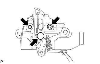
(b) Connect the hood lock control cable.
|
(c) Install the hood lock assembly with the 3 bolts. Torque: <A> Centering Bolt : 8.0 N·m {82 kgf·cm, 71 in·lbf} Torque: <A> Standard Bolt : 7.5 N·m {77 kgf·cm, 66 in·lbf} Torque: <B> : 8.0 N·m {82 kgf·cm, 71 in·lbf} |
|
|
(d) Install a new hood lock nut cap. |
|
6. INSTALL HOOD LOCK ASSEMBLY (w/ Engine Hood Courtesy Switch)
|
(a) Apply MP grease to the sliding areas of the lock. |
|
(b) Connect the hood lock control cable.
|
(c) Install the hood lock assembly with the 3 bolts. Torque: <A> Centering Bolt : 8.0 N·m {82 kgf·cm, 71 in·lbf} Torque: <A> Standard Bolt : 7.5 N·m {77 kgf·cm, 66 in·lbf} Torque: <B> : 8.0 N·m {82 kgf·cm, 71 in·lbf} |
|
(d) Connect the connector.
|
(e) Install a new hood lock nut cap. |
|
7. INSTALL LOW PITCHED HORN ASSEMBLY
8. INSTALL RADIATOR GRILLE
9. INSTALL COOL AIR INTAKE DUCT SEAL
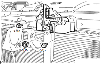
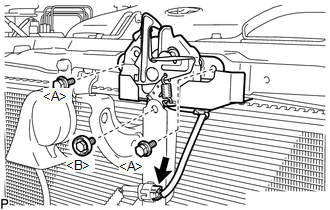
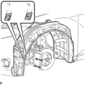
10. INSTALL FRONT FENDER LINER LH
(a) Install the front fender liner LH with new grommet.
(b) Install the 5 clips <A>.
(c) Install the clip <B>.
(d) Install the bolt and 6 clips.
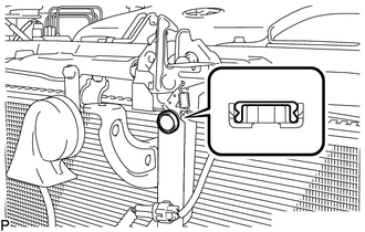
|
(e) Install the 2 pin hold clips. Text in Illustration
NOTICE: Insert the pin hold clip with the slot aligned vertically. Do not rotate the clip after inserting it. After installation, confirm that the slot is vertical. |
|
11. INSTALL FRONT WHEEL LH
12. INSTALL FRONT FENDER OUTSIDE MOULDING LH
13. INSPECT HOOD SUB-ASSEMBLY
14. ADJUST HOOD SUB-ASSEMBLY
 Components
COMPONENTS
ILLUSTRATION
ILLUSTRATION
...
 Removal
REMOVAL
PROCEDURE
1. REMOVE FRONT WHEEL LH
2. REMOVE FRONT FENDER OUTSIDE MOULDING LH
3. REMOVE FRONT FENDER LINER LH
(a) Using a screwdriver, turn the pin 90 degrees and remove the ...
Other materials about Toyota Venza:
Pressure Control Solenoid "C" Electrical (Shift Solenoid Valve SL3) (P0798)
DESCRIPTION
Changing from 1st to 6th is performed by the TCM turning shift solenoid valves
SL1, SL2, SL3, SL4 and SL on and off. If an open or short circuit occurs in any
of the shift solenoid valves, the TCM controls the remaining normal shift solenoid
...
Precaution
PRECAUTION
1. PRECAUTION FOR DISCONNECTING CABLE FROM NEGATIVE BATTERY TERMINAL
NOTICE:
After the ignition switch is turned off, the navigation receiver assembly
records various types of memory and settings. As a result, after turning
the ig ...
SRS Warning Light does not Come ON
DESCRIPTION
The SRS warning light is located on the combination meter assembly.
When the SRS is normal, the SRS warning light comes on for approximately 6 seconds
after the ignition switch is turned from off to ON, and then goes off automatically.
If ther ...

0.1427