Toyota Venza: Removal
REMOVAL
PROCEDURE
1. REMOVE FRONT SEAT ASSEMBLY LH
(See page .gif) )
)
2. REMOVE FRONT DOOR SCUFF PLATE LH
3. REMOVE COWL SIDE TRIM SUB-ASSEMBLY LH
4. REMOVE FRONT DOOR OPENING TRIM WEATHERSTRIP LH
5. REMOVE REAR DOOR SCUFF PLATE LH
6. REMOVE REAR DOOR OPENING TRIM WEATHERSTRIP LH
7. REMOVE LAP BELT OUTER ANCHOR COVER LH
8. DISCONNECT FRONT SEAT OUTER BELT ASSEMBLY LH
9. REMOVE LOWER CENTER PILLAR GARNISH LH
10. REMOVE TONNEAU COVER ASSEMBLY (w/ Tonneau Cover)
11. REMOVE DECK BOARD ASSEMBLY
12. REMOVE NO. 3 DECK BOARD SUB-ASSEMBLY
13. REMOVE DECK SIDE TRIM BOX LH
14. REMOVE NO. 2 DECK BOARD SUB-ASSEMBLY
15. REMOVE DECK SIDE TRIM BOX RH
16. REMOVE NO. 1 DECK BOARD
17. REMOVE REAR SEAT SUB FLOOR PANEL ASSEMBLY
18. REMOVE REAR FLOOR FINISH PLATE
19. REMOVE REAR SEAT HEADREST ASSEMBLY LH
20. REMOVE REAR SEAT INNER TRACK BRACKET COVER LH
21. REMOVE REAR SEAT OUTER TRACK BRACKET COVER LH
22. DISCONNECT REAR SEAT NO. 2 RECLINING CONTROL CABLE SUB-ASSEMBLY
23. REMOVE REAR SEAT ASSEMBLY LH
24. REMOVE RECLINING REMOTE CONTROL BEZEL LH
25. REMOVE LUGGAGE HOLD BELT STRIKER ASSEMBLY LH
26. DISCONNECT REAR SEAT OUTER BELT ASSEMBLY LH
27. REMOVE DECK TRIM SIDE PANEL ASSEMBLY LH
28. DISCONNECT FUEL LID LOCK OPEN LEVER SUB-ASSEMBLY
|
(a) Remove the bolt. |
|
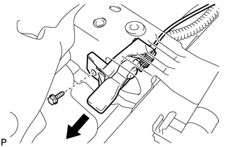
(b) Disconnect the fuel lid lock open lever sub-assembly as shown in the illustration.
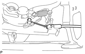
|
(c) Disconnect the fuel lid lock control cable sub-assembly. |
|
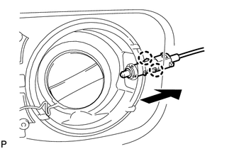
29. REMOVE FUEL LID LOCK CONTROL CABLE SUB-ASSEMBLY
|
(a) Disengage the 2 claws and disconnect the fuel lid lock control cable sub-assembly. |
|
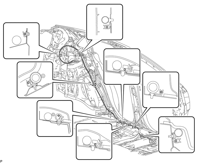
(b) Disengage the 8 clamps and remove the fuel lid lock control cable sub-assembly.
 Components
COMPONENTS
ILLUSTRATION
ILLUSTRATION
ILLUSTRATION
ILLUSTRATION
ILLUSTRATION
...
 Installation
INSTALLATION
PROCEDURE
1. INSTALL FUEL LID LOCK CONTROL CABLE SUB-ASSEMBLY
(a) Engage the 8 clamps.
(b) Engage the 2 claws and connect the fuel lid lock control cable sub-assembly.
...
Other materials about Toyota Venza:
Diagnosis System
DIAGNOSIS SYSTEM
1. DESCRIPTION
(a) The certification ECU (smart key ECU assembly) control the vehicle smart
key system functions. Smart key system data and Diagnostic Trouble Codes (DTCs)
can be read through the vehicle Data Link Connector 3 (DLC3). In ...
Pressure Control Solenoid "A" Performance (Shift Solenoid Valve SL1) (P0746)
SYSTEM DESCRIPTION
The TCM uses the vehicle speed signal and signals from the transmission speed
sensors (NC, NT) to detect the actual gear (1st, 2nd, 3rd, 4th, 5th or 6th gear).
Then the TCM compares the actual gear with the shift schedule in the TCM memo ...
System Voltage (P0560)
DESCRIPTION
The battery supplies electricity to the TCM even when the ignition switch is
off. This power allows the TCM to store data such as DTC history and freeze frame
data. If the battery voltage falls below a minimum level, these memories are cleared ...

0.1126