
Toyota Venza: Inspection
INSPECTION
PROCEDURE
1. INSPECT REAR WIPER MOTOR AND BRACKET ASSEMBLY
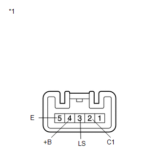
(a) Check the wiper low operation.
(1) Connect a battery positive (+) lead to terminal 4 (+B), and a negative (-) lead to terminal 3 (LS) and terminal 5 (E), and check that the motor operates.
OK:
Motor operates.
If the result is not as specified, replace the motor assembly.
(b) Check the intermittent operation.
(1) Connect a battery positive (+) lead to terminal 4 (+B), and a negative (-) lead to terminal 2 (C1) and terminal 5 (E), and check that the motor operates.
OK:
Motor operates.
If the result is not as specified, replace the rear wiper motor and bracket assembly.
Text in Illustration|
*1 |
Component without harness connected (Rear Wiper Motor and Bracket Assembly) |
 Removal
REMOVAL
PROCEDURE
1. REMOVE BACK DOOR PANEL TRIM ASSEMBLY
2. REMOVE REAR WIPER ARM HEAD CAP
(a) Disengage the 4 claws and remove the rear wiper arm head cap as shown
in the illus ...
 Installation
INSTALLATION
PROCEDURE
1. INSTALL REAR WIPER MOTOR AND BRACKET ASSEMBLY
(a) Install the rear wiper motor and bracket assembly with the 3 bolts.
Torque:
5.5 N·m {56 kgf·cm, 49 in ...
Other materials about Toyota Venza:
System Diagram
SYSTEM DIAGRAM
Communication Table
Transmitting ECU (Transmitter)
Receiving ECU (Receiver)
Signal
Line
Certification ECU
(Smart key ECU assembly)
Main body ECU
(Driver side junc ...
4wd Control Ecu
Components
COMPONENTS
ILLUSTRATION
Removal
REMOVAL
PROCEDURE
1. REMOVE FRONT DOOR SCUFF PLATE RH
2. REMOVE COWL SIDE TRIM SUB-ASSEMBLY RH
3. REMOVE NO. 2 INSTRUMENT PANEL UNDER COVER SUB-ASSEMBLY
4. REMOVE LOWER INSTRUMENT PANEL SUB-ASSEMBLY
...
Terminals Of Ecu
TERMINALS OF ECU
1. STEERING LOCK ECU (STEERING LOCK ACTUATOR ASSEMBLY)
Terminal No. (Symbol)
Wiring Color
Terminal Description
Condition
Specified Condition
D17-1 (GND) - Body ground
...

0.1619