Toyota Venza: Removal
REMOVAL
CAUTION / NOTICE / HINT
HINT:
- Use the same procedure for the RH side and LH side.
- The procedure listed below is for the LH side.
PROCEDURE
1. REMOVE REAR WHEEL
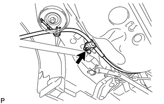
2. SEPARATE NO. 3 PARKING BRAKE CABLE ASSEMBLY
|
(a) Remove the bolt and separate the No. 3 parking brake cable assembly. |
|
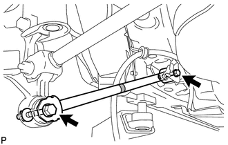
3. REMOVE REAR STRUT ROD ASSEMBLY (for 2WD)
|
(a) Remove the 2 bolts, the 2 nuts and the rear strut rod assembly. NOTICE: Since stopper nuts are used, loosen the bolts. |
|
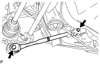
4. REMOVE REAR STRUT ROD ASSEMBLY (for AWD)
|
(a) Remove the 2 bolts, the 2 nuts and the rear strut rod assembly. NOTICE: Since stopper nuts are used, loosen the bolts. |
|
 Components
COMPONENTS
ILLUSTRATION
ILLUSTRATION
...
 Installation
INSTALLATION
CAUTION / NOTICE / HINT
HINT:
Use the same procedure for the RH side and LH side.
The procedure listed below is for the LH side.
PROCEDURE
1. INSTALL REAR STRUT ROD ...
Other materials about Toyota Venza:
Runnable Signal Malfunction (B2286,P0335)
DESCRIPTION
The power management control ECU receives an engine speed signal and information
that indicates whether the engine is running or not. It receives the engine speed
signal from the ECM via a direct line, and the information about whether the eng ...
Adjustment
ADJUSTMENT
PROCEDURE
1. INSPECT AND ADJUST BRAKE PEDAL HEIGHT
(a) Check the brake pedal height.
(1) Turn back the carpet.
(2) Measure the brake pedal height from the dash panel to the bottom
edge of the brake pedal pad.
Text in Illustrat ...
Under Hood
General Maintenance
GENERAL MAINTENANCE
PROCEDURE
1. GENERAL NOTES
Maintenance requirements vary depending on the country.
Check the maintenance schedule in the owner's manual supplement.
Following the maintenance schedule is mandat ...

0.1254