Toyota Venza: Installation
INSTALLATION
CAUTION / NOTICE / HINT
HINT:
- Use the same procedure for the RH side and LH side.
- The procedure listed below is for the LH side.
PROCEDURE
1. INSTALL REAR STRUT ROD ASSEMBLY (for 2WD)
|
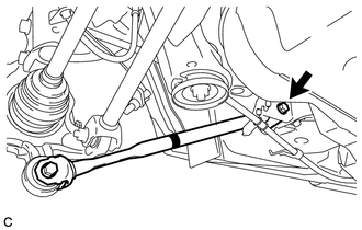
(a) Temporarily install the rear strut rod assembly to the rear axle carrier sub-assembly with the bolt and the nut. Text in Illustration
NOTICE:
|
|
|
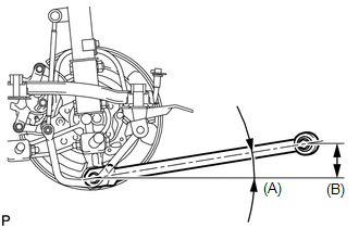
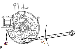
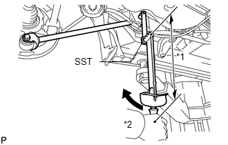
(b) Set the rear strut rod assembly in the tightening position shown in the illustration. Standard angle (A): 9°54' (9.9°) Standard length (B): 83.9 mm (3.30 in.) |
|
|
(c) Fully tighten the bolt in the tightening position. Torque: 80 N·m {816 kgf·cm, 59 ft·lbf} |
|
|
(d) Temporarily install the rear strut rod assembly to the body with the bolt and the nut. |
|
|
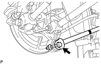
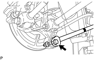
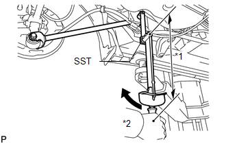
(e) Using SST and a socket wrench (17 mm), fully tighten the bolt in the rebound position. Text in Illustration
SST: 09961-00950 Torque: Specified Tightening Torque : 80 N·m {816 kgf·cm, 59 ft·lbf} NOTICE:
HINT:
|
|
.gif) ).
). 
2. INSTALL REAR STRUT ROD ASSEMBLY (for AWD)
|
(a) Temporarily install the rear strut rod assembly to the rear axle carrier sub-assembly with the bolt and the nut. Text in Illustration
NOTICE:
|
|
|
(b) Set the rear strut rod assembly in the tightening position shown in the illustration. Standard angle (A): 9°3' (9.04°) Standard length (B): 78.3 mm (3.08 in.) |
|
|
(c) Fully tighten the bolt in the tightening position. Torque: 80 N·m {816 kgf·cm, 59 ft·lbf} |
|
|
(d) Temporarily install the rear strut rod assembly to the body with the bolt and the nut. |
|
|
(e) Using SST and a socket wrench (17 mm), fully tighten the bolt in the rebound position. Text in Illustration
SST: 09961-00950 Torque: Specified Tightening Torque : 80 N·m {816 kgf·cm, 59 ft·lbf} NOTICE:
HINT:
|
|
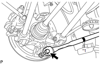
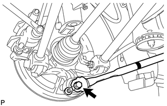
3. INSTALL NO. 3 PARKING BRAKE CABLE ASSEMBLY
|
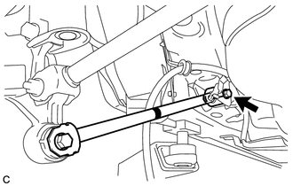
(a) Install the No. 3 parking brake cable assembly with the bolt. Torque: 6.0 N·m {61 kgf·cm, 53 in·lbf} NOTICE: Do not twist the No. 3 parking brake cable assembly when installing it. |
|
.png)
4. INSTALL REAR WHEEL
Torque:
103 N·m {1050 kgf·cm, 76 ft·lbf}
5. STABILIZE SUSPENSION
(a) Lower the vehicle to the ground.
(b) Bounce the vehicle up and down at the corners to stabilize the rear suspension.
 Removal
REMOVAL
CAUTION / NOTICE / HINT
HINT:
Use the same procedure for the RH side and LH side.
The procedure listed below is for the LH side.
PROCEDURE
1. REMOVE REAR WHEEL
2. SEPAR ...

Other materials about Toyota Venza:
Room Light
Components
COMPONENTS
ILLUSTRATION
Removal
REMOVAL
PROCEDURE
1. REMOVE SPOT LIGHT ASSEMBLY
(a) Using a screwdriver with its tip wrapped with protective tape, disengage
the 8 claws to remove the 2 spot light lenses.
Text in Illust ...
Installation
INSTALLATION
PROCEDURE
1. INSPECT TORQUE CONVERTER ASSEMBLY
2. INSTALL TORQUE CONVERTER ASSEMBLY
(a) Engage the splines of the input shaft and turbine runner.
(b) Engage the splines o ...
Back Door Entry Unlock Function does not Operate
DESCRIPTION
If the entry back door open function does not operate but the back door entry
lock function operates, the communication between the vehicle and key is normal.
As a faulty part, the back door open switch circuit (from the back door opener switc ...

0.1533