Toyota Venza: Rocker Panel Moulding
Components
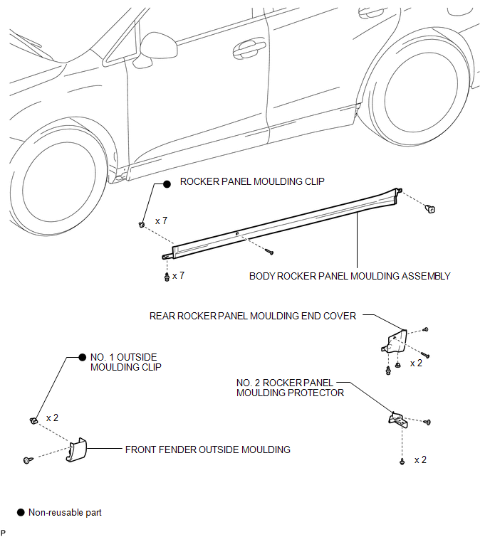
COMPONENTS
ILLUSTRATION
Removal
REMOVAL
PROCEDURE
1. REMOVE FRONT FENDER OUTSIDE MOULDING
.gif)
2. REMOVE NO. 2 ROCKER PANEL MOULDING PROTECTOR
3. REMOVE REAR ROCKER PANEL MOULDING END COVER
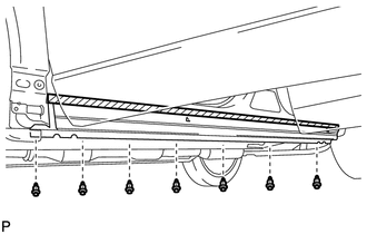
4. REMOVE BODY ROCKER PANEL MOULDING ASSEMBLY
|
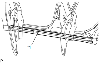
(a) Put protective tape around the body rocker panel moulding assembly. Text in Illustration
|
|
|
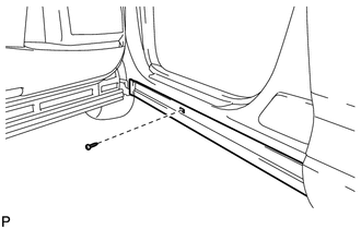
(b) Remove the screw. |
|
|
(c) Remove the grommet. |
|
|
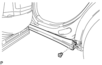
(d) Remove the 7 clips. |
|
|
(e) Disengage the 7 clips to remove the body rocker panel moulding assembly. |
|
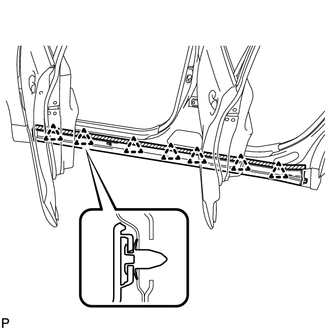
(f) Remove the 7 clips (rocker panel moulding clip).
Installation
INSTALLATION
PROCEDURE
1. INSTALL BODY ROCKER PANEL MOULDING ASSEMBLY
(a) Install 7 new clips (rocker panel moulding clip) to the body rocker panel moulding assembly.
|
(b) Engage the 7 clips to install the body rocker panel moulding assembly. |
|
.png)
|
(c) Install the screw. |
|
.png)
|
(d) Install the grommet. |
|
.png)
|
(e) Install the 7 clips. |
|
.png)
2. INSTALL REAR ROCKER PANEL MOULDING END COVER
.gif)
3. INSTALL NO. 2 ROCKER PANEL MOULDING PROTECTOR
4. INSTALL FRONT FENDER OUTSIDE MOULDING
 Rear Wheel House Plate
Components
COMPONENTS
ILLUSTRATION
Installation
INSTALLATION
PROCEDURE
1. INSTALL NO. 2 ROCKER PANEL MOULDING PROTECTOR
(a) Install the No. 2 rocker panel moulding protector wi ...

Other materials about Toyota Venza:
Using the automatic mode
Press
.
The air conditioning system will begin to operate. In outside air or recirculated
air mode, air outlets, fan speed and air conditioning on/ off are automatically
adjusted according to the temperature setting.
“AUTO” will be displayed on th ...
Diagnosis System
DIAGNOSIS SYSTEM
1. DESCRIPTION
(a) When troubleshooting a vehicle with a diagnosis system, the only difference
from the usual troubleshooting procedure is connecting the Techstream to the vehicle
and reading various data output from the clearance warnin ...
Disposal
DISPOSAL
PROCEDURE
1. DISPOSE OF FRONT SHOCK ABSORBER ASSEMBLY
(a) Position the front shock absorber assembly level with the piston
rod fully extended. Using a drill, make a hole in the cylinder between A
and B as shown in the illustratio ...

0.172