Toyota Venza: Installation
INSTALLATION
PROCEDURE
1. TEMPORARILY INSTALL REAR STABILIZER BAR BRACKET LH (for Front Side)
|
(a) Temporarily install the rear stabilizer bar bracket LH (front side) with the bolt. HINT: Loosely tighten the bolt so that the bracket can be moved by hand. |
|
.png)
2. TEMPORARILY INSTALL REAR STABILIZER BAR BRACKET RH (for Front Side)
|
(a) Temporarily install the rear stabilizer bar bracket RH (front side) with the 2 bolts. HINT: Loosely tighten the bolts so that the bracket can be moved by hand. |
|
.png)
3. INSTALL REAR STABILIZER BUSHING (for LH Side)
|
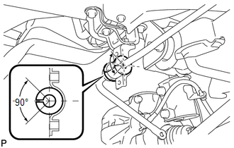
(a) Install the rear stabilizer bushing (LH side) to the rear stabilizer bar. NOTICE: Make sure that the cutout of the rear stabilizer bushing is positioned within the range shown in the illustration. |
|
4. INSTALL REAR STABILIZER BUSHING (for RH Side)
|
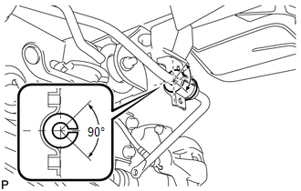
(a) Install the rear stabilizer bushing (RH side) to the rear stabilizer bar. NOTICE: Make sure that the cutout of the rear stabilizer bushing is positioned within the range shown in the illustration. |
|
5. INSTALL REAR STABILIZER BAR BRACKET LH (for Rear Side)
|
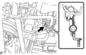
(a) Install the rear stabilizer bar bracket LH (rear side) with the 2 bolts. Torque: 19 N·m {194 kgf·cm, 14 ft·lbf} |
|
.png)
6. INSTALL REAR STABILIZER BAR BRACKET RH (for Rear Side)
|
(a) Install the rear stabilizer bar bracket RH (rear side) with the 2 bolts. Torque: 19 N·m {194 kgf·cm, 14 ft·lbf} |
|
.png)
7. FULLY TIGHTEN REAR STABILIZER BAR BRACKET LH (for Front Side)
|
(a) Fully tighten the bolt. Torque: 54 N·m {551 kgf·cm, 40 ft·lbf} |
|
8. FULLY TIGHTEN REAR STABILIZER BAR BRACKET RH (for Front Side)
|
(a) Fully tighten the 2 bolts. Torque: 19 N·m {194 kgf·cm, 14 ft·lbf} |
|
9. INSTALL REAR LOWER SUSPENSION BRACE (for LH Side)
|
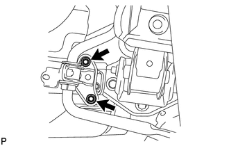
(a) Install the rear lower suspension brace with the bolt and the nut. Torque: 35 N·m {357 kgf·cm, 26 ft·lbf} |
|
.png)
10. INSTALL REAR LOWER SUSPENSION BRACE (for RH Side)
HINT:
Perform the same procedure as the LH side.
11. INSTALL NO. 1 FLOOR UNDER COVER
.gif)
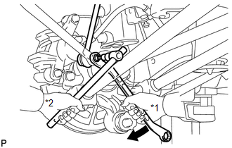
12. INSTALL REAR STABILIZER LINK ASSEMBLY LH
|
(a) Install the rear stabilizer link assembly LH to the rear shock absorber with coil spring LH with the nut. Text in Illustration
Torque: 39 N·m {400 kgf·cm, 29 ft·lbf} HINT: If the ball joint turns together with the nut, use a hexagon wrench (5 mm) to hold the stud bolt. |
|
.png)
|
(b) Install the rear stabilizer link assembly LH to the rear stabilizer bar with the nut. Text in Illustration
Torque: 39 N·m {400 kgf·cm, 29 ft·lbf} HINT: If the ball joint turns together with the nut, use a hexagon wrench (5 mm) to hold the stud bolt. |
|
13. INSTALL REAR STABILIZER LINK ASSEMBLY RH
HINT:
Perform the same procedure as the LH side.
14. INSTALL REAR WHEELS
Torque:
103 N·m {1050 kgf·cm, 76 ft·lbf}
 Removal
REMOVAL
PROCEDURE
1. REMOVE REAR WHEELS
2. REMOVE REAR STABILIZER LINK ASSEMBLY LH
(a) Remove the nut and separate the rear stabilizer link assembly LH
from the rear stabilizer bar. ...
 Rear Strut Rod
...
Other materials about Toyota Venza:
Freeze Frame Data
FREEZE FRAME DATA
1. FREEZE FRAME DATA
(a) Whenever a DTC is detected, the AFS ECU (headlight swivel ECU assembly) stores
the current vehicle (sensor) state as Freeze Frame Data.
2. CHECK FREEZE FRAME DATA
(a) Connect the Techstream to the DLC3.
(b) Tur ...
Customizing the features by using the multi-information display (vehicles with
TFT type multi-information display)
Press the “SETUP” button while the vehicle is stopped.
The “Custom Settings” screen is displayed on the multi-information display.
If left idle for approximately 10 seconds, the display will revert to the previous
screen.
Select the setting yo ...
Removal
REMOVAL
CAUTION / NOTICE / HINT
HINT:
The front side fix window assembly can be reused. When installing the
window, if any of the clips on the front side fix window assembly are broken,
butyl tape can be used to support the glass until the a ...

0.1152