Toyota Venza: Removal
REMOVAL
CAUTION / NOTICE / HINT
HINT:
- Use the same procedure for the RH side and LH side.
- The procedure listed below is for the LH side.
PROCEDURE
1. REMOVE REAR WHEEL
2. REMOVE DECK SIDE TRIM
|
(a) Disengage the 5 claws, and then remove the deck side trim. |
|
3. SEPARATE REAR FLEXIBLE HOSE (for 2WD)
|
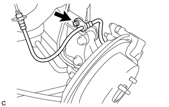
(a) Remove the bolt and separate the rear flexible hose from the rear shock absorber with coil spring. |
|
4. SEPARATE REAR FLEXIBLE HOSE (for AWD)
|
(a) Remove the bolt and separate the rear flexible hose from the rear shock absorber with coil spring. |
|
5. SEPARATE REAR SPEED SENSOR WIRE (for 2WD)
|
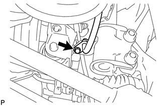
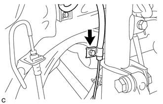
(a) Remove the bolt and separate the rear speed sensor wire from the rear shock absorber with coil spring. |
|
6. SEPARATE REAR SPEED SENSOR (for AWD)
|
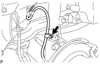
(a) Remove the bolt and separate the rear speed sensor from the rear shock absorber with coil spring. |
|
7. SEPARATE REAR STABILIZER LINK ASSEMBLY (for 2WD)
|
(a) Remove the nut and separate the rear stabilizer link assembly from the rear shock absorber with coil spring. Text in Illustration
HINT: If the ball joint turns together with the nut, use a hexagon wrench (5 mm) to hold the stud bolt. |
|
8. SEPARATE REAR STABILIZER LINK ASSEMBLY (for AWD)
|
(a) Remove the nut and separate the rear stabilizer link assembly from the rear shock absorber with coil spring. Text in Illustration
HINT: If the ball joint turns together with the nut, use a hexagon wrench (5 mm) to hold the stud bolt. |
|
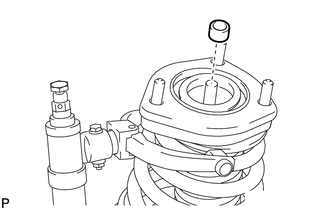
9. REMOVE REAR NO. 1 SUSPENSION SUPPORT COVER
|
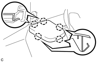
(a) Disengage the 4 claws and remove the rear No. 1 suspension support cover. |
|
10. REMOVE REAR SHOCK ABSORBER WITH COIL SPRING (for 2WD)
|
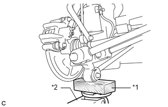
(a) Support the rear axle carrier sub-assembly using a jack and wooden block as shown in the illustration. Text in Illustration
NOTICE: Do not deform the brake dust cover. HINT: Support the rear axle carrier sub-assembly until reinstallation of the rear shock absorber with coil spring is complete. |
|
.png)
|
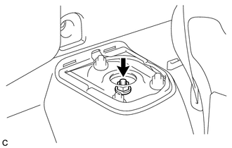
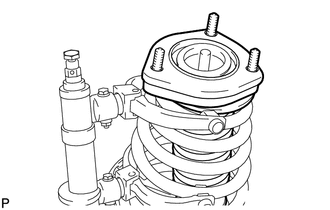
(b) Loosen the rear support to rear shock absorber nut. CAUTION: Do not remove the rear support to rear shock absorber nut. NOTICE: Loosen the nut only when the rear shock absorber with coil spring needs to be disassembled. |
|
|
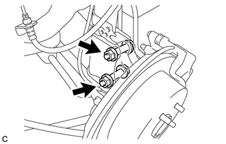
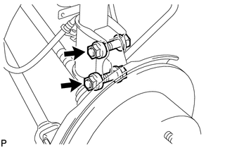
(c) Remove the 2 bolts and 2 nuts, and separate the rear shock absorber with coil spring from the rear axle carrier sub-assembly. NOTICE: When removing the nuts, keep the bolts from rotating. |
|
|
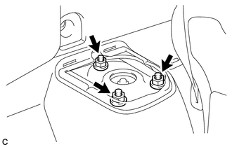
(d) Remove the 3 nuts and rear shock absorber with coil spring. NOTICE: Make sure that the rear speed sensor and rear flexible hose are disconnected from the rear shock absorber with coil spring. |
|
11. REMOVE REAR SHOCK ABSORBER WITH COIL SPRING (for AWD)
|
(a) Support the rear axle carrier sub-assembly using a jack and wooden block as shown in the illustration. Text in Illustration
NOTICE: Do not deform the brake dust cover. HINT: Support the rear axle carrier sub-assembly until reinstallation of the rear shock absorber with coil spring is complete. |
|
|
(b) Loosen the rear support to rear shock absorber nut. CAUTION: Do not remove the rear support to rear shock absorber nut. NOTICE: Loosen the nut only when the rear shock absorber with coil spring needs to be disassembled. |
|
|
(c) Remove the 2 bolts and 2 nuts, and separate the rear shock absorber with coil spring from the rear axle carrier sub-assembly. NOTICE: When removing the nuts, keep the bolts from rotating. |
|
|
(d) Remove the 3 nuts and rear shock absorber with coil spring. NOTICE: Make sure that the rear speed sensor and rear flexible hose are disconnected from the rear shock absorber with coil spring. |
|
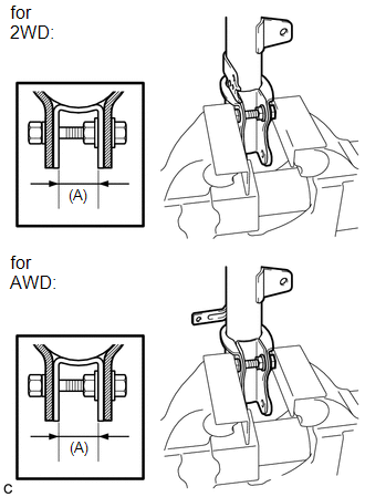
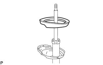
12. SECURE REAR SHOCK ABSORBER WITH COIL SPRING
|
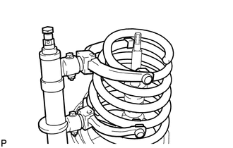
(a) Install the bolt and nut to the rear shock absorber with coil spring as shown in the illustration and secure the rear shock absorber with coil spring in a vise. Length (A): 28 mm (1.10 in.) |
|
13. REMOVE REAR SUPPORT TO REAR SHOCK ABSORBER NUT
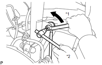
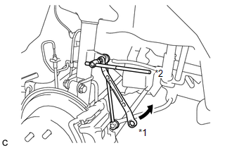
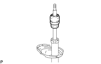
(a) Using SST, compress the rear coil spring.
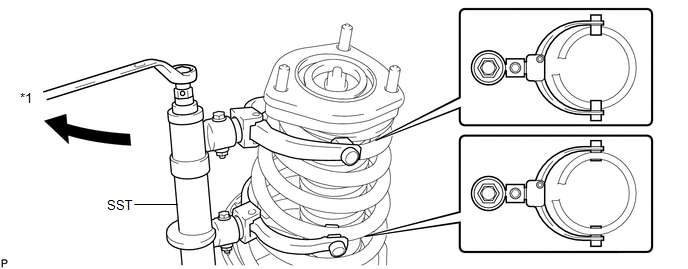 Text in Illustration
|
*1 |
Turn |
SST: 09727-30021
09727-00010
09727-00021
09727-00031
NOTICE:
Do not use an impact wrench. It will damage SST.
(b) Check that the rear coil spring is fully compressed.
|
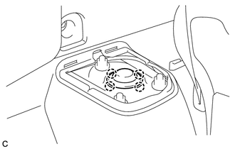
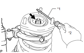
(c) Using a screwdriver or an equivalent tool to hold the rear suspension support assembly, remove the rear support to rear shock absorber nut from the rear shock absorber assembly. Text in Illustration
HINT: Tape the screwdriver or the equivalent tool before use. |
|
14. REMOVE REAR SUPPORT TO REAR SHOCK ABSORBER COLLAR
|
(a) Remove the rear support to rear shock absorber collar from the rear shock absorber assembly. |
|
15. REMOVE REAR SUSPENSION SUPPORT ASSEMBLY
|
(a) Remove the rear suspension support assembly from the rear shock absorber assembly. |
|
16. REMOVE REAR COIL SPRING
|
(a) Remove the rear coil spring together with SST from the rear shock absorber assembly. |
|
17. REMOVE REAR NO. 1 SPRING BUMPER
|
(a) Remove the rear No. 1 spring bumper from the rear shock absorber assembly. |
|
18. REMOVE REAR LOWER COIL SPRING INSULATOR
|
(a) Remove the rear lower coil spring insulator from the rear shock absorber assembly. |
|
 Inspection
INSPECTION
PROCEDURE
1. INSPECT REAR SHOCK ABSORBER ASSEMBLY
(a) Compress and extend the shock absorber rod 4 or more times.
Standard:
There is no abnormal resistance or sound and ...
 Installation
INSTALLATION
CAUTION / NOTICE / HINT
HINT:
Use the same procedure for the RH side and LH side.
The procedure listed below is for the LH side.
PROCEDURE
1. SECURE REAR SHOCK ABSO ...
Other materials about Toyota Venza:
If the engine will not start
If the engine still does not start after following the correct starting procedure
(, 175) or releasing the steering lock (, 176), confirm the following points.
- The engine will not start even if you are carrying the correct key.
One of the followi ...
Replacement
REPLACEMENT
PROCEDURE
1. REPLACE RING PIN
NOTICE:
It is not necessary to remove the ring pin unless it is being replaced.
(a) Remove the 12 ring pins.
(b) Using a plastic-faced hammer, install 12 new ring pins.
Standard Protrusion Height:
...
Mute Signal Circuit between Navigation Receiver Assembly and Stereo Component
Amplifier
DESCRIPTION
This circuit sends a signal to the stereo component amplifier assembly to mute
noise. Due to this, the noise produced by changing the sound source ceases.
If there is an open in the circuit, noise can be heard from the speakers when
changing ...

0.1415