Toyota Venza: Replacement
REPLACEMENT
PROCEDURE
1. REPLACE RING PIN
NOTICE:
It is not necessary to remove the ring pin unless it is being replaced.
(a) Remove the 12 ring pins.
(b) Using a plastic-faced hammer, install 12 new ring pins.
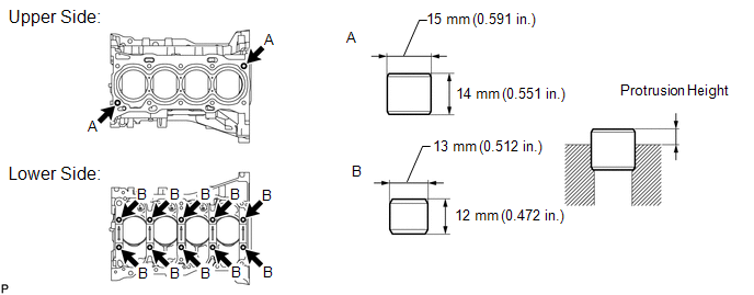
Standard Protrusion Height:
|
Item |
Specified Condition |
|---|---|
|
A |
5.0 to 7.0 mm (0.197 to 0.276 in.) |
|
B |
4.0 to 7.0 mm (0.157 to 0.276 in.) |
2. REPLACE STRAIGHT PIN
NOTICE:
It is not necessary to remove the straight pin unless it is being replaced.
(a) Remove the 14 straight pins.
(b) Using a plastic-faced hammer, install 14 new straight pins.
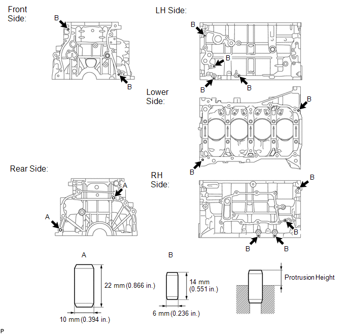
Standard Protrusion Height:
|
Item |
Specified Condition |
|---|---|
|
A |
11.0 to 13.0 mm (0.433 to 0.512 in.) |
|
B |
5.0 to 7.0 mm (0.197 to 0.276 in.) |
 Reassembly
REASSEMBLY
CAUTION / NOTICE / HINT
HINT:
Perform "Inspection After Repair" after replacing the piston or piston ring (See
page ).
PROCEDURE
1. INSTALL STUD BOLT
NOTICE:
If a stud b ...
 Cylinder Head
...
Other materials about Toyota Venza:
Removal
REMOVAL
PROCEDURE
1. REMOVE FRONT SEAT HEADREST ASSEMBLY
2. REMOVE FRONT SEAT REAR OUTER TRACK COVER
3. REMOVE FRONT SEAT REAR INNER TRACK COVER
4. REMOVE FRONT SEAT ASSEMBLY
5. REMOVE RECLINING POWER SEAT SWITCH KNOB
6. REMOVE SLIDE AND VER ...
Installation
INSTALLATION
PROCEDURE
1. INSTALL NO. 2 WINDSHIELD GLASS STOPPER
(a) Using a brush or a sponge, coat the application area of 2 new No. 2 windshield
glass stoppers with Primer G.
NOTICE:
Do not apply too much primer.
Allow the primer to dry f ...
Diagnostic Trouble Code Chart
DIAGNOSTIC TROUBLE CODE CHART
HINT:
If a trouble code is stored during the DTC check, inspect the trouble areas listed
for that code. For details of the code, refer to the "See page" below.
Main Body
DTC Code
Detection Ite ...

0.1535