Toyota Venza: Removal
REMOVAL
CAUTION / NOTICE / HINT
NOTICE:
When disconnecting the steering intermediate shaft assembly and pinion shaft of steering gear assembly, be sure to place matchmarks before servicing.
PROCEDURE
1. PLACE FRONT WHEELS FACING STRAIGHT AHEAD
2. SECURE STEERING WHEEL
|
(a) Secure the steering wheel with the seat belt in order to prevent it from rotating. HINT: This operation is necessary to prevent damage to the spiral cable. |
|
.png)
3. REMOVE FRONT WHEELS
4. SEPARATE STEERING INTERMEDIATE SHAFT ASSEMBLY
|
(a) Remove the bolt and slide the steering intermediate shaft assembly. NOTICE: Do not separate the steering intermediate shaft assembly from the steering link assembly. |
|
.png)
|
(b) Put matchmarks on the steering intermediate shaft assembly and steering link assembly. Text in Illustration
|
|
.png)
(c) Separate the steering intermediate shaft assembly from the steering link assembly.
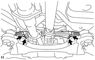
5. SEPARATE TIE ROD ASSEMBLY LH
|
(a) Remove the cotter pin and nut. |
|
.png)
|
(b) Install SST to the tie rod end. SST: 09960-20010 09961-02060 NOTICE: Make sure that the upper ends of the tie rod end and SST are aligned. |
|
.png)
(c) Using SST, separate the tie rod end from the steering knuckle.
.png) Text in Illustration
Text in Illustration
|
*1 |
Tie the string without allowing for any slack. |
|
*2 |
Place the wrench here. |
|
*3 |
Turn |
SST: 09960-20010
09961-02010
CAUTION:
Apply grease to the threads and end of the SST bolt.
NOTICE:
- When securing SST to the steering knuckle, be sure to tighten SST using a string to prevent it from falling.
- Install SST so that A and B are parallel.
- Be sure to place a wrench on the part indicated in the illustration.
- Do not damage the front disc brake dust cover.
- Do not damage the ball joint dust cover.
- Do not damage the steering knuckle.
6. SEPARATE TIE ROD ASSEMBLY RH
HINT:
Perform the same procedure as for the LH side.
7. SEPARATE FRONT NO. 1 STABILIZER BRACKET LH
.gif)
8. SEPARATE FRONT NO. 1 STABILIZER BRACKET RH
HINT:
Perform the same procedure as for the LH side.
9. SEPARATE FRONT STABILIZER BAR WITH BRACKET
10. SEPARATE STEERING LINK ASSEMBLY
|
(a) Remove the 2 bolts, 2 nuts and separate the steering link assembly from the front frame assembly. NOTICE:
|
|
11. REMOVE FRONT FRAME ASSEMBLY
- for 1AR-FE: (See page )
- for 2GR-FE: (See page )
12. REMOVE STEERING LINK ASSEMBLY
(a) Remove the steering link assembly from the vehicle.
13. REMOVE TIE ROD ASSEMBLY LH
|
(a) Put matchmarks on the tie rod assembly LH and steering rack end sub-assembly. Text in Illustration
|
|
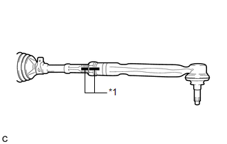
(b) Loosen the lock nut, and remove the tie rod assembly LH and lock nut.
14. REMOVE TIE ROD ASSEMBLY RH
HINT:
Perform the same procedure as for the LH side.
 Components
COMPONENTS
ILLUSTRATION
ILLUSTRATION
ILLUSTRATION
ILLUSTRATION
...
 Disassembly
DISASSEMBLY
PROCEDURE
1. REMOVE STEERING RACK BOOT CLIP (for LH Side)
(a) Using pliers, remove the steering rack boot clip.
2. REMOVE STEERING RACK BOOT CLIP (for RH Side)
HINT:
Perform the same ...
Other materials about Toyota Venza:
Data List / Active Test
DATA LIST / ACTIVE TEST
1. DATA LIST
HINT:
Using the Techstream to read the Data List allows the values or states of switches,
sensors, actuators and other items to be read without removing any parts. This non-intrusive
inspection can be very useful bec ...
Diagnosis System
DIAGNOSIS SYSTEM
1. CHECK DLC3
(a) Check the DLC3 (See page ).
2. FUNCTION OF PASSENGER AIRBAG ON/OFF INDICATOR
(a) Initial check.
(1) Turn the ignition switch to ON.
(2) The passenger airbag ON/OFF indicator ("ON" and "OFF") comes o ...
Basic Inspection
BASIC INSPECTION
When the malfunction is not confirmed by the DTC check, troubleshooting should
be carried out in all circuits considered to be possible causes of the problem.
In many cases, by carrying out the basic engine check shown in the following pr ...

0.1691