Toyota Venza: Components
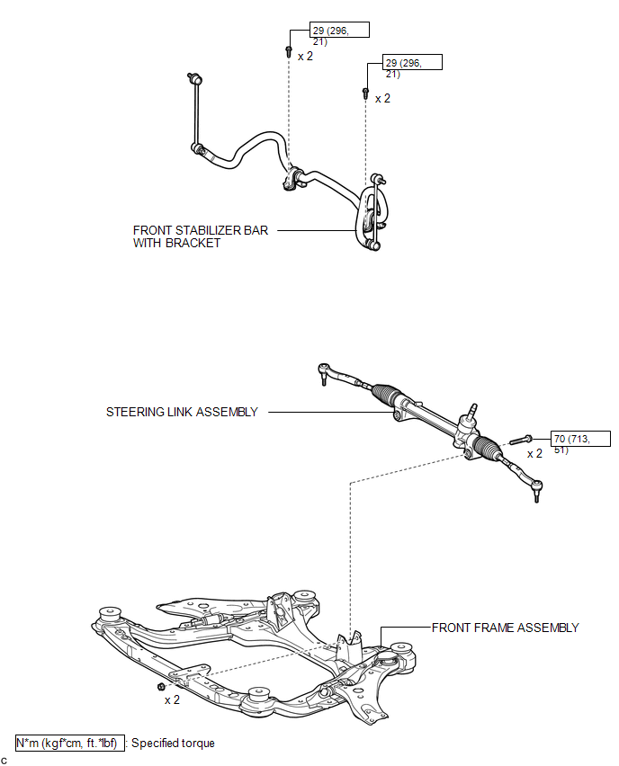
COMPONENTS
ILLUSTRATION
.png)
ILLUSTRATION
ILLUSTRATION
.png)
ILLUSTRATION
.png)

 Removal
REMOVAL
CAUTION / NOTICE / HINT
NOTICE:
When disconnecting the steering intermediate shaft assembly and pinion shaft
of steering gear assembly, be sure to place matchmarks before servicing.
PROC ...
Other materials about Toyota Venza:
System Diagram
SYSTEM DIAGRAM
Communication Table
Sender
Receiver
Signal
Line
ECM
Combination Meter ECU
CRUISE main indicator operation signal
SET indicator operation sig ...
Precaution
PRECAUTION
1. PRECAUTION FOR DISCONNECTING CABLE FROM NEGATIVE BATTERY TERMINAL
NOTICE:
When disconnecting the cable from the negative (-) battery terminal, initialize
the following system after the terminal is reconnected:
System Name
...
Reassembly
REASSEMBLY
PROCEDURE
1. INSTALL NO. 3 ANTENNA CORD SUB-ASSEMBLY
2. INSTALL ROOF HEADLINING ASSEMBLY
HINT:
Refer to the procedure from Install Roof Headlining Assembly (See page
).
3. INSTALL REAR WIPER MOTOR AND BRACKET ASSEMBLY
4. INSTALL REAR ...

0.1361