Toyota Venza: Removal
REMOVAL
PROCEDURE
1. REMOVE FRONT WIPER ARM HEAD CAP
.gif)
2. REMOVE FRONT WIPER ARM AND BLADE ASSEMBLY LH
3. REMOVE FRONT WIPER ARM AND BLADE ASSEMBLY RH
4. REMOVE FRONT FENDER TO COWL SIDE SEAL LH
5. REMOVE FRONT FENDER TO COWL SIDE SEAL RH
6. REMOVE COWL TOP VENTILATOR LOUVER SUB-ASSEMBLY
7. REMOVE WINDSHIELD WIPER MOTOR AND LINK ASSEMBLY
8. REMOVE OUTER COWL TOP PANEL
9. REMOVE NO. 1 ENGINE COVER SUB-ASSEMBLY
10. REMOVE VACUUM SWITCHING VALVE ASSEMBLY (for ACIS)
|
(a) Disconnect the 2 vacuum hoses, clamp and connector. |
|
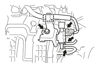
(b) Remove the bolt and vacuum switching valve assembly (for ACIS).
 Inspection
INSPECTION
PROCEDURE
1. INSPECT VACUUM SWITCHING VALVE ASSEMBLY (for ACIS)
(a) Measure the resistance according to the value(s) in the table below.
Text in Illustration
...
 Installation
INSTALLATION
PROCEDURE
1. INSTALL VACUUM SWITCHING VALVE ASSEMBLY (for ACIS)
(a) Install the vacuum switching valve assembly (for ACIS) with the bolt.
Torque:
9.0 N·m {92 kgf·cm ...
Other materials about Toyota Venza:
Front Speed Sensor RH Circuit (C0200/31,C0205/32,C1271/71,C1272/72,C1330/35,C1331/36)
DESCRIPTION
The speed sensor detects wheel speed and sends the appropriate signals to the
skid control ECU. These signals are used for the ABS control system.
Speed sensor rotors have 48 serrations. The hall IC type speed sensor use the
frequency of outp ...
Under Hood
General Maintenance
GENERAL MAINTENANCE
PROCEDURE
1. GENERAL NOTES
Maintenance requirements vary depending on the country.
Check the maintenance schedule in the owner's manual supplement.
Following the maintenance schedule is mandat ...
Reassembly
REASSEMBLY
PROCEDURE
1. INSTALL NO. 14 ROOF SILENCER PAD
(a) Align the markings on the roof headlining assembly with the No. 14 roof silencer
pad and install the silencer pad using hot-melt glue as shown in the illustration.
2. INSTALL NO. 1 ROOF WIRE ...

0.1605