Toyota Venza: Power Back Door Warning Buzzer
Components
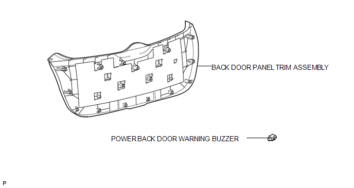
COMPONENTS
ILLUSTRATION
Inspection
INSPECTION
PROCEDURE
1. INSPECT POWER BACK DOOR WARNING BUZZER
|
(a) Measure the resistance according to the value(s) in the table below. HINT: If battery voltage is applied directly to the buzzer, the buzzer will not sound. Standard Resistance:
If the result is not as specified, replace the power back door warning buzzer. |
|
.png)
Removal
REMOVAL
PROCEDURE
1. REMOVE BACK DOOR PANEL TRIM ASSEMBLY
.gif)
2. REMOVE POWER BACK DOOR WARNING BUZZER
|
(a) Disconnect the connector. |
|
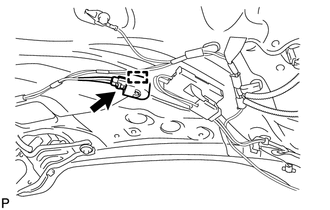
(b) Disengage the clamp to remove the power back door warning buzzer.
Installation
INSTALLATION
PROCEDURE
1. INSTALL POWER BACK DOOR WARNING BUZZER
|
(a) Engage the clamp to install the power back door warning buzzer. |
|
.png)
(b) Connect the connector.
2. INSTALL BACK DOOR PANEL TRIM ASSEMBLY
.gif)
 Power Back Door Touch Sensor
Components
COMPONENTS
ILLUSTRATION
Removal
REMOVAL
PROCEDURE
1. REMOVE UPPER BACK WINDOW PANEL TRIM
2. REMOVE BACK DOOR PANEL TRIM ASSEMBLY
3. DISCONNECT POWER BACK DOOR ROD (for L ...
 Rear Door
...
Other materials about Toyota Venza:
Removal
REMOVAL
PROCEDURE
1. PRECAUTION
(See page )
NOTICE:
After turning the ignition switch off, waiting time may be required before disconnecting
the cable from the negative (-) battery terminal. Therefore, make sure to read the
disconnecting the cable fr ...
Installation
INSTALLATION
PROCEDURE
1. CLEAN FRONT SIDE FIX WINDOW ASSEMBLY
(a) Clean the outer edges of the front side fix window assembly with
a non-residue solvent.
NOTICE:
Do not touch the glass surface after cleaning it.
Be c ...
Torque Sensor Zero Point Adjustment Undone (C1515,C1525)
DESCRIPTION
These DTCs do not indicate a malfunction. The power steering ECU stores these
DTCs when it determines that the rotation angle sensor value initialization and
torque sensor zero point calibration have not been performed.
DTC No.
...

0.1428