Toyota Venza: Removal
REMOVAL
PROCEDURE
1. DISCHARGE FUEL SYSTEM PRESSURE
HINT:
(See page .gif) ).
).
2. DISCONNECT CABLE FROM NEGATIVE BATTERY TERMINAL
CAUTION:
When disconnecting the cable, some systems need to be initialized after the cable
is reconnected (See page ).
3. REMOVE THROTTLE BODY ASSEMBLY
(a) Remove the throttle body assembly (See page
).
4. REMOVE VACUUM SWITCHING VALVE ASSEMBLY (for ACIS)
|
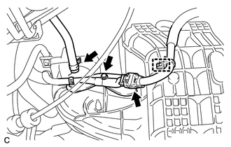
(a) Disconnect the 2 vacuum hoses, 2 union to connector tube hoses, clamp and connector. |
|
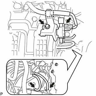
(b) Remove the bolt and vacuum switching valve assembly (for ACIS).
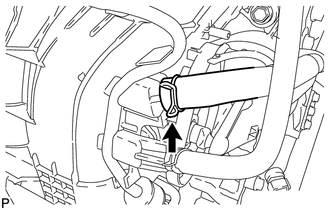
5. DISCONNECT NO. 2 VENTILATION HOSE
|
(a) Disconnect the No. 2 ventilation hose from the intake manifold. |
|
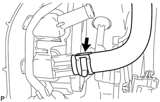
6. REMOVE UNION TO CONNECTOR TUBE HOSE
|
(a) Remove the union to connector tube hose from the intake manifold. |
|
7. REMOVE FUEL DELIVERY PIPE SUB-ASSEMBLY
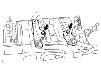
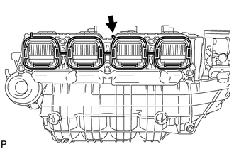
8. REMOVE INTAKE MANIFOLD
|
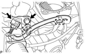
(a) Remove the 2 bolts and 2 wire harness brackets. |
|
|
(b) Disconnect the fuel vapor feed hose, clamp and connector. |
|
(c) Remove the bolt and wire harness bracket.
|
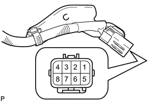
(d) Apply battery voltage to the terminals of the connector to close the tumble control valves. Standard:
NOTICE:
|
|
|
(e) Remove the bolt. |
|
(f) Detach the 2 clamps from the intake manifold and bracket.
(g) Disconnect the intake air control valve actuator connector.
|
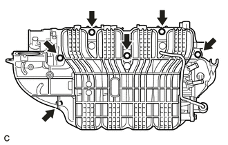
(h) Remove the 6 bolts and intake manifold. NOTICE: The tumble control valves may be damaged if they are not closed before installing the intake manifold. HINT: Connect the battery to the terminals of the actuator to operate the motor
and close the valves (See page |
|
|
(i) Remove the intake manifold gasket from the intake manifold. |
|
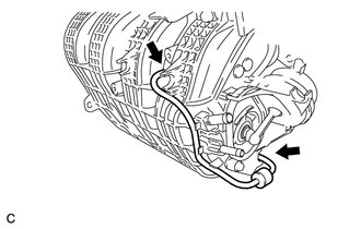
9. REMOVE CHECK VALVE
|
(a) Disconnect the 2 vacuum hoses from the intake manifold and remove the check valve. |
|
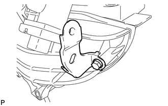
10. REMOVE WIRING HARNESS CLAMP BRACKET
|
(a) Remove the bolt and wiring harness clamp bracket. |
|
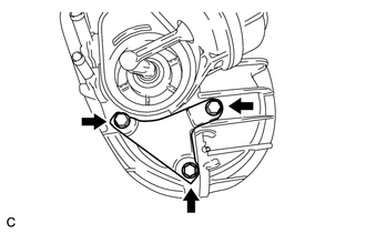
11. REMOVE ENGINE MOUNTING DAMPER
|
(a) Remove the 3 bolts and engine mounting damper. |
|
 Components
COMPONENTS
ILLUSTRATION
ILLUSTRATION
ILLUSTRATION
...
 Inspection
INSPECTION
PROCEDURE
1. INSPECT INTAKE AIR CONTROL VALVE (for ACIS)
(a) Inspect the diaphragm.
(1) Using a vacuum pump, apply a vacuum of 60 kPa (450 mmHg, 17.7 in.Hg)
or higher to ...
Other materials about Toyota Venza:
On-vehicle Inspection
ON-VEHICLE INSPECTION
PROCEDURE
1. INSPECT WINDSHIELD WIPER MOTOR ASSEMBLY
(a) for RH Side
(1) Operate the windshield wiper motor assembly.
(2) Stop the windshield wiper motor assembly operation.
...
PBD Pulse Sensor Malfunction (B2222)
DESCRIPTION
A pulse sensor is built into the power back door ECU (power back door
motor unit) to detect foreign objects and the back door position. The pulse
sensor monitors the operating speed of the back door to detect foreign objects.
Th ...
Inspection
INSPECTION
PROCEDURE
1. INSPECT SHIFT LOCK CONTROL UNIT ASSEMBLY (w/o Smart Key System)
(a) Measure the voltage according to the value(s) in the table below.
Text in Illustration
*1
Component with harness c ...

0.1292