Toyota Venza: Components
COMPONENTS
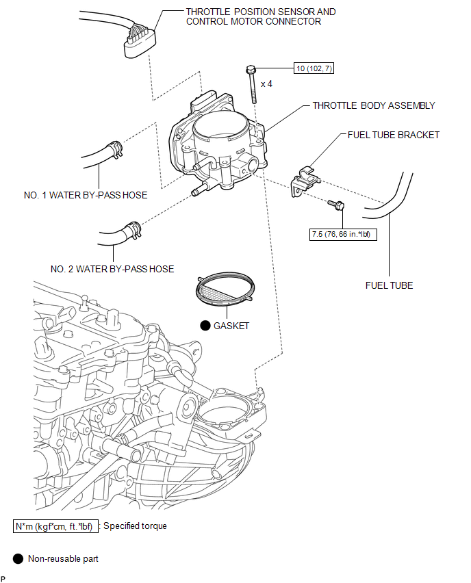
ILLUSTRATION
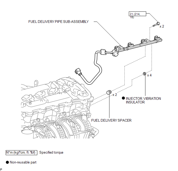
ILLUSTRATION
ILLUSTRATION
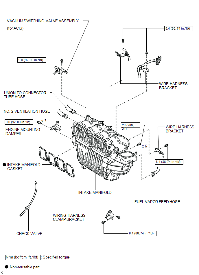
 Intake Manifold
...
 Removal
REMOVAL
PROCEDURE
1. DISCHARGE FUEL SYSTEM PRESSURE
HINT:
(See page ).
2. DISCONNECT CABLE FROM NEGATIVE BATTERY TERMINAL
CAUTION:
When disconnecting the cable, some systems need to be initial ...
Other materials about Toyota Venza:
Inspection
INSPECTION
PROCEDURE
1. INSPECT PRELOAD
(a) Using SST and a torque wrench, measure the preload of the backlash
between the driven pinion and ring gear.
SST: 09326-20011
Preload (at Starting):
Item
P ...
System Diagram
SYSTEM DIAGRAM
Communication Table
Sender
Receiver
Signal
Line
ECM
Navigation Receiver Assembly*1
Radio and Display Receiver Assembly*2
Reverse sig ...
Rear Airbag Sensor RH Circuit Malfunction (B1630/23)
DESCRIPTION
The side collision sensor RH circuit (to determine deployment of the front seat
side airbag assembly RH and curtain shield airbag assembly RH) is composed of the
center airbag sensor assembly, rear airbag sensor RH and side airbag sensor RH.
...

0.1728