Toyota Venza: Inspection
INSPECTION
PROCEDURE
1. INSPECT INTAKE AIR CONTROL VALVE (for ACIS)
(a) Inspect the diaphragm.
|
(1) Using a vacuum pump, apply a vacuum of 60 kPa (450 mmHg, 17.7 in.Hg) or higher to the diaphragm chamber. Wait for 1 minute and check that the needle of the vacuum pump does not lower. If the result is not as specified, replace the intake manifold. |
|
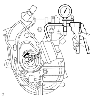
(b) After applying vacuum in the step above, check that the actuator rod operates.
2. INSPECT VACUUM TANK AND CHECK VALVE
|
(a) Disconnect the vacuum hose from the check valve. |
|
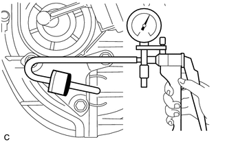
(b) Using a vacuum pump, apply vacuum to the check valve. Wait for 1 minute and check that the needle of the vacuum pump does not lower.
If the result is not as specified, replace the check valve.
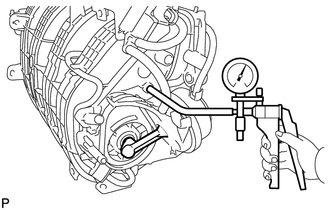
(c) Connect the vacuum hose to the check valve.
|
(d) Using a vacuum pump, apply a vacuum of 60 kPa (450 mmHg, 17.7 in.Hg) or higher to the vacuum tank. Wait for 1 minute and check that the needle of the vacuum pump does not lower. If the result is not as specified, replace the intake manifold. |
|
 Removal
REMOVAL
PROCEDURE
1. DISCHARGE FUEL SYSTEM PRESSURE
HINT:
(See page ).
2. DISCONNECT CABLE FROM NEGATIVE BATTERY TERMINAL
CAUTION:
When disconnecting the cable, some systems need to be initial ...
 Installation
INSTALLATION
PROCEDURE
1. INSTALL ENGINE MOUNTING DAMPER
(a) Install the engine mounting damper with the 3 bolts.
Torque:
9.0 N·m {92 kgf·cm, 80 in·lbf}
...
Other materials about Toyota Venza:
Front Fog Light Circuit
DESCRIPTION
The main body ECU (driver side junction block assembly) controls the fog light
relay.
WIRING DIAGRAM
CAUTION / NOTICE / HINT
NOTICE:
Inspect the fuses for circuits related to this system before performing the following
inspection procedu ...
If you think something is wrong
If you notice any of the following symptoms, your vehicle probably needs adjustment
or repair. Contact your Toyota dealer as soon as possible.
- Visible symptoms
• Fluid leaks under the vehicle
(Water dripping from the air conditioning after use i ...
Height Control Sensor
Components
COMPONENTS
ILLUSTRATION
ILLUSTRATION
Removal
REMOVAL
PROCEDURE
1. REMOVE REAR HEIGHT CONTROL SENSOR SUB-ASSEMBLY (for 2WD)
(a) Disconnect the connector.
(b) Remove the 3 nuts ...

0.1576