Toyota Venza: Installation
INSTALLATION
PROCEDURE
1. INSTALL HEATED OXYGEN SENSOR
.gif)
2. INSTALL FRONT EXHAUST PIPE ASSEMBLY
|
(a) Using a vernier caliper, measure the free length of the compression springs. Minimum Free Length: 41.5 mm (1.63 in.) If the free length is less than the minimum, replace the compression spring. |
|
.png)
(b) Temporarily install a new gasket to the exhaust manifold converter sub-assembly.
|
(c) Using a plastic hammer and wooden block, tap in the gasket until its surface is flush with the exhaust manifold converter sub-assembly. Text in Illustration
NOTICE:
|
|
.png)
|
(d) Install the front exhaust pipe assembly to the exhaust manifold converter sub-assembly with the 2 bolts and 2 compression springs. Torque: 43 N·m {438 kgf·cm, 32 ft·lbf} |
|
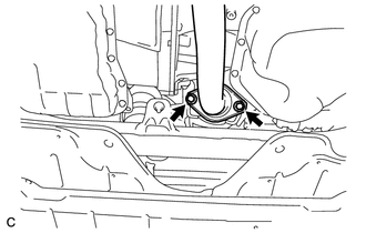
(e) Connect the heated oxygen sensor connector.
3. INSTALL CENTER EXHAUST PIPE ASSEMBLY
(a) Install a new gasket to the center exhaust pipe assembly.
(b) Connect the center exhaust pipe assembly to the 2 exhaust pipe supports.
|
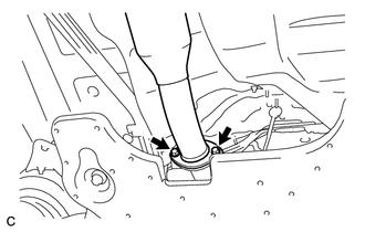
(c) Install the center exhaust pipe assembly to the front exhaust pipe assembly with the 2 bolts. Torque: 43 N·m {438 kgf·cm, 32 ft·lbf} |
|
4. INSTALL TAIL EXHAUST PIPE ASSEMBLY
|
(a) Using a vernier caliper, measure the free length of the compression springs. Minimum Free Length: 38.5 mm (1.52 in.) If the free length is less than the minimum, replace the compression spring. |
|
(b) Temporarily install a new gasket to the center exhaust pipe assembly.
|
(c) Using a plastic hammer and wooden block, tap in the gasket until its surface is flush with the center exhaust pipe assembly. Text in Illustration
NOTICE:
|
|
(d) Connect the tail exhaust pipe assembly to the 4 exhaust pipe supports.
|
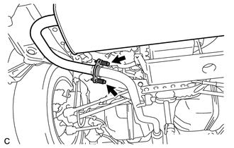
(e) Install the tail exhaust pipe assembly to the center exhaust pipe assembly with the 2 bolts and 2 compression springs. Torque: 43 N·m {438 kgf·cm, 32 ft·lbf} |
|
5. INSTALL TAIL EXHAUST PIPE BAFFLE SUB-ASSEMBLY
|
(a) Align the cutout of the tail exhaust pipe baffle sub-assembly with the protrusion of the tail exhaust pipe assembly as shown in the illustration. Text in Illustration
|
|
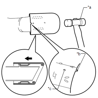
(b) Using a plastic hammer, uniformly tap the tail exhaust pipe baffle sub-assembly onto the tail exhaust pipe assembly.
6. INSPECT FOR EXHAUST GAS LEAK
If gas is leaking, tighten the areas necessary to stop the leak. Replace damaged parts as necessary.
(a) Perform "Inspection After Repair" after repairing an exhaust gas leak (See
page ).
 Components
COMPONENTS
ILLUSTRATION
...
 Removal
REMOVAL
CAUTION / NOTICE / HINT
CAUTION:
Wear protective gloves when removing the exhaust pipe.
The exhaust pipe is extremely hot immediately after the engine has stopped.
...
Other materials about Toyota Venza:
Installation
INSTALLATION
PROCEDURE
1. INSTALL FRONT SUSPENSION MEMBER BODY MOUNTING REAR CUSHION LH
(a) Temporarily install a new front suspension member body mounting rear
cushion LH while confirming the installation direction.
NOTICE:
Position th ...
Selecting the units
Press the “US/M-M” button.
The unit changes each time the button is pressed.
- Liquid crystal display
Small spots or light spots may appear on the display. This phenomenon is characteristic
of liquid crystal displays, and there is no problem to ...
Installation
INSTALLATION
PROCEDURE
1. INSTALL TELEVISION CAMERA ASSEMBLY (w/ Rear View Monitor System)
2. INSTALL BACK DOOR OPENER SWITCH ASSEMBLY
3. INSTALL NO. 1 BACK DOOR EMBLEM
4. INSTALL NO. 2 BACK DOOR NAME PLATE
5. INSTALL BACK DOOR OUTSIDE GARNIS ...

0.1353