Toyota Venza: Intake Air Control Valve Actuator(for Tcv)
Components
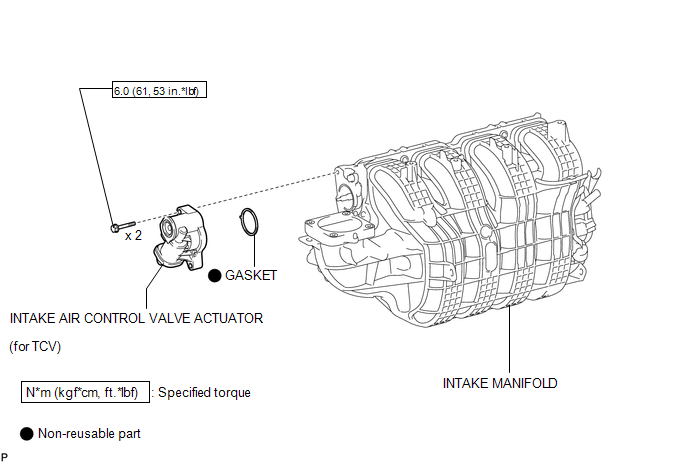
COMPONENTS
ILLUSTRATION
Removal
REMOVAL
PROCEDURE
1. REMOVE INTAKE MANIFOLD
(a) Remove the intake manifold (See page .gif) ).
).
2. REMOVE INTAKE AIR CONTROL VALVE ACTUATOR (for TCV)
(a) Remove the 2 bolts, intake air control valve actuator and gasket from the intake manifold.
NOTICE:
- Make sure that foreign matter, such as water, oil, sand and iron particles,
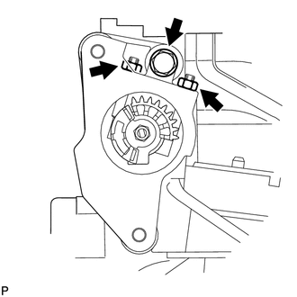
does not enter the gear chamber or actuator at the locations marked by the
circles in the illustration.
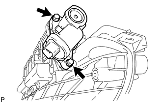
- Do not loosen or remove the bolt and 2 nuts shown in the illustration.
Inspection
INSPECTION
PROCEDURE
1. INSPECT INTAKE AIR CONTROL VALVE ACTUATOR (for TCV)
(a) Check the intake air control valve actuator operation.
|
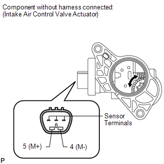
(1) Check that the motor operates when the battery is connected to the terminals of the intake air control valve actuator. NOTICE: If the positive (+) and negative (-) battery leads contact the sensor terminals, the actuator may be damaged. Standard:
If the result is not as specified, replace the intake air control valve actuator. |
|
Installation
INSTALLATION
PROCEDURE
1. INSTALL INTAKE AIR CONTROL VALVE ACTUATOR (for TCV)
NOTICE:
- Make sure that foreign matter, such as water, oil, sand and iron particles,
does not enter the gear chamber or actuator at the locations marked by the
circles in the illustration.
.png)
- Do not loosen or remove the bolt and 2 nuts shown in the illustration.
.png)
|
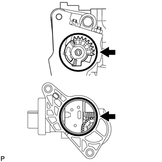
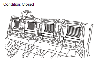
(a) Close the tumble control valves. HINT: If the tumble control valves are not closed, close them by hand. |
|
|
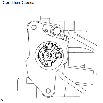
(b) Check that the gear of each tumble control valve is in the position shown in the illustration. HINT: Turn the gear clockwise until it contacts the stopper. |
|
(c) Install a new gasket to the intake air control valve actuator.
|
(d) Install the intake air control valve actuator to the intake manifold with the 2 bolts. Torque: 6.0 N·m {61 kgf·cm, 53 in·lbf} NOTICE:
|
|
.png)
2. INSTALL INTAKE MANIFOLD
(a) Install the intake manifold (See page .gif)
).
 Removal
REMOVAL
CAUTION / NOTICE / HINT
CAUTION:
Wear protective gloves when removing the exhaust pipe.
The exhaust pipe is extremely hot immediately after the engine has stopped.
...
 Intake Manifold
...
Other materials about Toyota Venza:
Random Access Memory (RAM) (P0604)
MONITOR DESCRIPTION
The ECM continuously monitors its internal memory status. This self-check ensures
that the ECM is functioning properly. It is diagnosed by internal "mirroring" of
the main CPU and sub CPU to detect Random Access Memory (RAM) ...
Diagnosis System
DIAGNOSIS SYSTEM
1. CHECK DLC3
(a) Check the DLC3 (See page ).
2. FUNCTION OF P/S WARNING LIGHT
(a) When a malfunction is detected in the power steering system, the P/S warning
light on the accessory meter comes on to inform the driver of the malfunctio ...
Diagnostic Trouble Code Chart
DIAGNOSTIC TROUBLE CODE CHART
HINT:
If a DTC is displayed during the DTC check, check the parts listed in
the table below and proceed to the "See page" given.
If multiple suspected areas are listed, the potential causes of the
s ...

0.1251