Toyota Venza: Removal
REMOVAL
PROCEDURE
1. REMOVE ENGINE ASSEMBLY WITH TRANSAXLE
(a) Remove the engine and transaxle (See page
.gif) ).
).
2. REMOVE EXHAUST MANIFOLD CONVERTER SUB-ASSEMBLY
(a) Remove the exhaust manifold converter (See page
).
3. REMOVE THROTTLE BODY ASSEMBLY
4. REMOVE FUEL DELIVERY PIPE SUB-ASSEMBLY
5. DISCONNECT NO. 2 VENTILATION HOSE
6. REMOVE INTAKE MANIFOLD
7. REMOVE TIMING CHAIN COVER SUB-ASSEMBLY
(See page )
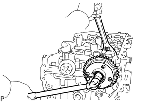
8. SET NO. 1 CYLINDER TO TDC/COMPRESSION
(a) Temporarily install the crankshaft pulley bolt.
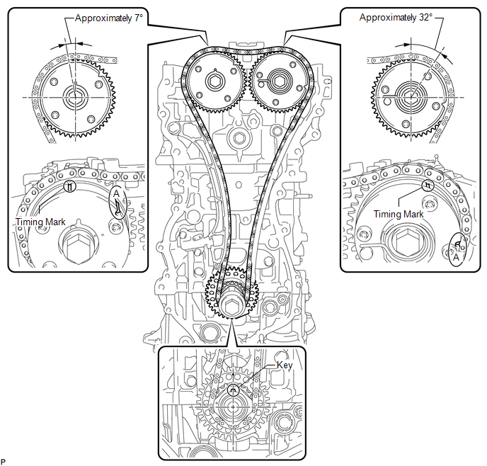
HINT:
"A" is not a timing mark.
(b) Rotate the crankshaft clockwise so that the timing marks on the crankshaft timing gear and camshaft timing gears are as shown in the illustration.
HINT:
If the timing marks do not align, rotate the crankshaft clockwise again and align the timing marks.
(c) Remove the crankshaft pulley bolt.
9. REMOVE TIMING CHAIN GUIDE
|
(a) Remove the bolt and timing chain guide. |
|
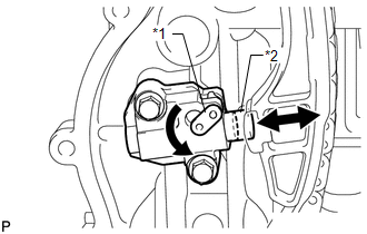
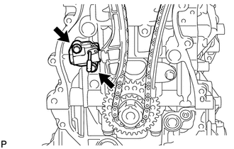
10. REMOVE NO. 1 CHAIN TENSIONER ASSEMBLY
|
(a) Allow the plunger to extend slightly, and then rotate the stopper plate counterclockwise to release the lock. Once the lock is released, push the plunger into the tensioner. Text in Illustration
|
|
|
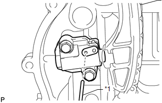
(b) Move the stopper plate clockwise to set the lock, and insert a pin into the stopper plate hole. Text in Illustration
|
|
|
(c) Remove the 2 bolts, chain tensioner and gasket. |
|
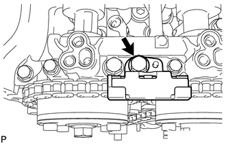
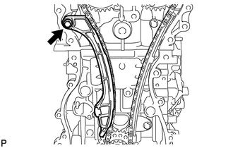
11. REMOVE CHAIN TENSIONER SLIPPER
|
(a) Remove the bolt and chain tensioner slipper. |
|
12. REMOVE CHAIN SUB-ASSEMBLY
(a) Remove the chain sub-assembly.
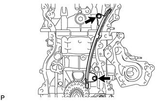
13. REMOVE NO. 1 CHAIN VIBRATION DAMPER
|
(a) Remove the 2 bolts and chain vibration damper. |
|
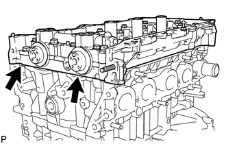
14. REMOVE CAMSHAFT TIMING GEAR ASSEMBLY
|
(a) Hold the hexagonal portion of the camshaft with a wrench and remove the bolt and camshaft timing gear. NOTICE:
|
|
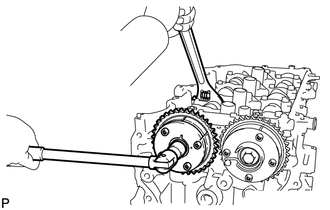
15. REMOVE CAMSHAFT TIMING EXHAUST GEAR ASSEMBLY
|
(a) Hold the hexagonal portion of the camshaft with a wrench and remove the bolt and camshaft timing exhaust gear. NOTICE:
|
|
16. REMOVE CAMSHAFT HOUSING SUB-ASSEMBLY
|
(a) Uniformly loosen and remove the 20 bearing cap bolts in the sequence shown in the illustration. |
|
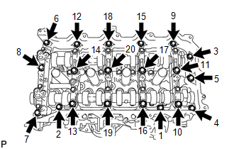
|
(b) Remove the camshaft housing by prying between the cylinder head and camshaft housing with a screwdriver. HINT: Tape the screwdriver tip before use. NOTICE: Be careful not to damage the contact surfaces of the cylinder head and camshaft housing. |
|
17. REMOVE CAMSHAFT BEARING CAP
|
(a) Remove the 11 bearing cap bolts in the sequence shown in the illustration. |
|
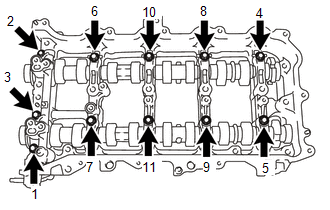
(b) Remove the 5 bearing caps.
HINT:
Arrange the removed parts in the correct order.
18. REMOVE OIL CONTROL VALVE FILTER
19. REMOVE NO. 1 CAMSHAFT BEARING
20. REMOVE CAMSHAFT
(a) Remove the No. 1 and No. 2 camshafts.
21. REMOVE NO. 2 CAMSHAFT BEARING
22. REMOVE NO. 1 VALVE ROCKER ARM SUB-ASSEMBLY
(a) Remove the 16 valve rocker arms from the cylinder head.
HINT:
Arrange the removed parts in the correct order.
23. REMOVE VALVE LASH ADJUSTER ASSEMBLY
(a) Remove the 16 valve lash adjusters from the cylinder head.
HINT:
Arrange the removed parts in the correct order.
24. REMOVE VALVE STEM CAP
(a) Remove the 16 valve stem caps from the cylinder head.
HINT:
Arrange the removed parts in the correct order.
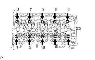
25. REMOVE CYLINDER HEAD SUB-ASSEMBLY
|
(a) Using a 10 mm bi-hexagon wrench, uniformly loosen the 10 bolts in the sequence shown in the illustration. Remove the 10 cylinder head bolts and plate washers. HINT: Be sure to keep the removed parts separate for each installation position. NOTICE:
|
|
(b) Remove the cylinder head.
26. REMOVE CYLINDER HEAD GASKET
(a) Remove the cylinder head gasket from the cylinder block.
 Components
COMPONENTS
ILLUSTRATION
ILLUSTRATION
ILLUSTRATION
ILLUSTRATION
ILLUSTRATION
ILLUSTRATION
...
 Installation
INSTALLATION
CAUTION / NOTICE / HINT
HINT:
Perform "Inspection After Repair" after replacing the camshaft, No. 2 camshaft,
camshaft timing gear assembly, camshaft timing exhaust gear as ...
Other materials about Toyota Venza:
Data List / Active Test
DATA LIST / ACTIVE TEST
1. DATA LIST
HINT:
Using the Techstream to read the Data List allows the values or states of switches,
sensors, actuators and other items to be read without removing any parts. This non-intrusive
inspection can be very useful bec ...
Wireless Transmitter Memory Function does not Operate
DESCRIPTION
With the ignition switch off and the driver door closed, pressing the manual
lock or unlock switch on the power window regulator master switch assembly while
holding a seat memory switch (M1 switch or M2 switch) will register the transmitter
...
Winter driving tips
Carry out the necessary preparations and inspections before driving the vehicle
in winter. Always drive the vehicle in a manner appropriate to the prevailing weather
conditions.
- Pre-winter preparations
• Use fluids that are appropriate to the p ...

0.1334