Toyota Venza: Installation
INSTALLATION
CAUTION / NOTICE / HINT
HINT:
Perform "Inspection After Repair" after replacing the camshaft, No. 2 camshaft,
camshaft timing gear assembly, camshaft timing exhaust gear assembly or cylinder
head sub-assembly (See page .gif) ).
).
PROCEDURE
1. INSPECT CYLINDER HEAD BOLT
2. INSPECT CYLINDER HEAD SUB-ASSEMBLY
3. INSTALL CYLINDER HEAD GASKET
(a) Clean the cylinder block and cylinder head sub-assembly with solvent.
 Text in Illustration
|
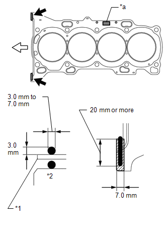
*1 |
Cylinder Head Gasket |
|
*2 |
Cylinder Block |
|
*a |
Lot No. |
.png) |
Seal Packing |
.png) |
Front |
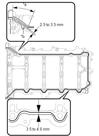
(b) Apply a continuous line of seal packing to a new cylinder head gasket as shown in the illustration.
Seal Packing:
Toyota Genuine Seal Packing Black, Three Bond 1207B or equivalent
Standard Seal Dimension:
3.0 to 7.0 mm (0.118 to 0.276 in.) wide and 3.0 mm (0.118 in.) thick
HINT:
Apply at least 20 mm (0.787 in.) of seal packing from the inside edge of the protrusion of the cylinder block.
NOTICE:
- Remove any oil from the contact surface.
- Install the cylinder head gasket within 3 minutes and tighten the bolts within 15 minutes of applying seal packing.
(c) Place a new cylinder head gasket on the cylinder block surface with the Lot No. stamp facing upward.
NOTICE:
Pay attention to the installation direction.
4. INSTALL CYLINDER HEAD SUB-ASSEMBLY
HINT:
The cylinder head bolts are tightened in 4 progressive steps.
(a) Place the cylinder head sub-assembly on the cylinder block.
NOTICE:
- Ensure that no oil is on the mounting surface of the cylinder head sub-assembly.
- Place the cylinder head sub-assembly on the cylinder block gently in order not to damage the gasket with the bottom part of the head.
(b) Install the plate washers to the cylinder head bolts.
(c) Apply a light coat of engine oil to the threads and under the heads of the cylinder head bolts.
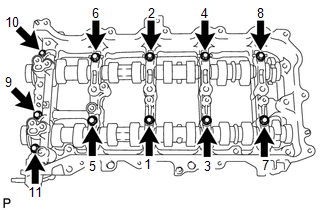
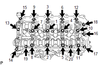
(d) Step 1:
|
(1) Using a 10 mm bi-hexagon wrench, install and uniformly tighten the 10 cylinder head bolts in several steps, in the sequence shown in the illustration. Torque: 36 N·m {367 kgf·cm, 27 ft·lbf} NOTICE: Do not drop the plate washers for the cylinder head bolts into the cylinder head sub-assembly. |
|
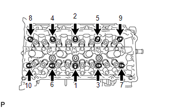
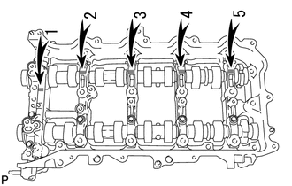
(e) Step 2:
(1) Tighten the cylinder head bolts again in the sequence shown in the illustration to make sure that they are tightened to the specified torque.
Torque:
36 N·m {367 kgf·cm, 27 ft·lbf}
(f) Step 3:
(1) Mark each cylinder head bolt head with paint as shown in the illustration.
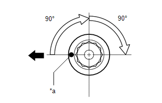 Text in Illustration
|
*a |
Paint Mark |
|
|
Front |
(2) Tighten the cylinder head bolts 90° in the sequence shown in step 1.
(g) Step 4:
(1) Tighten the cylinder head bolts another 90° in the sequence shown in step 1.
(2) Check that the painted marks are now facing rearward.
NOTICE:
- Do not apply oil for at least 4 hours after the installation.
- Do not start the engine for at least 4 hours after the installation.
- After the installation, if the seal packing has seeped out, wipe it off.
HINT:
Perform "Inspection After Repair" after replacing the cylinder head sub-assembly
(See page ).
5. INSTALL VALVE STEM CAP
(a) Apply a light coat of engine oil to the valve stem ends.
(b) Install the 16 valve stem caps to the cylinder head sub-assembly.
NOTICE:
Do not drop the valve stem caps into the cylinder head sub-assembly.
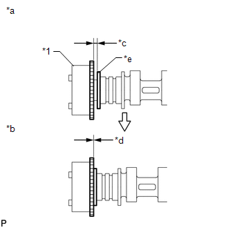
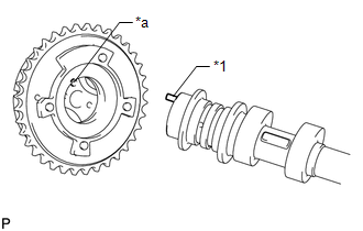
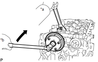
6. SET CAMSHAFT TIMING GEAR ASSEMBLY
HINT:
When installing the camshaft timing gear assembly, release the lock pin and set the camshaft timing gear assembly to the advanced position before installation.
|
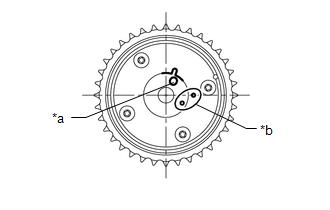
(a) Check the camshaft timing gear assembly position. Text in Illustration
NOTICE: If the camshaft timing gear assembly is set to the advanced position, do not let the camshaft timing gear assembly rotate clockwise during installation. If the camshaft timing gear assembly rotates to the retarded position, release the lock pin and set the camshaft timing gear assembly to the advanced position. |
|
|
(b) Align and attach the knock pin of the No. 1 camshaft with the pin hole of the camshaft timing gear assembly. Text in Illustration
|
|

|
(c) Check that there is no clearance between the camshaft timing gear assembly and camshaft flange. Text in Illustration
|
|
(d) Secure the camshaft in place by hand, and then install the installation bolt of the camshaft timing gear assembly by hand.
NOTICE:
Do not use any tools to install the bolt. If the bolt is installed using a tool, the lock pin will be damaged.
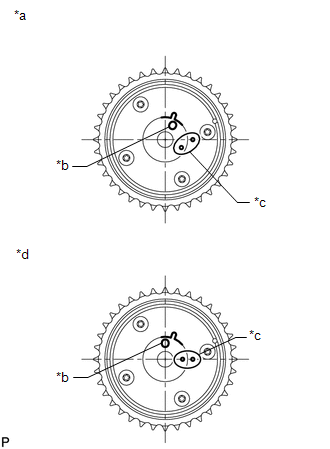
(e) Release the lock pin.
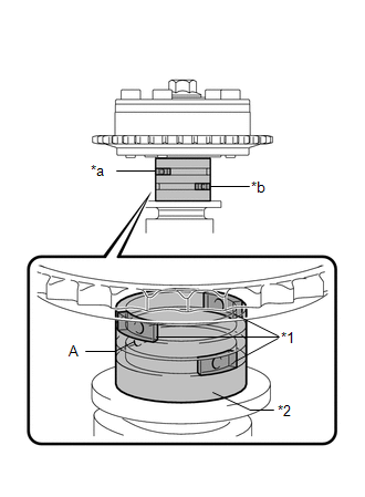 Text in Illustration
|
*1 |
Rubber |
|
*2 |
Vinyl Tape |
|
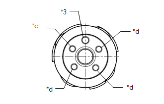
*3 |
Knock Pin |
|
*a |
Retard Side Path |
|
*b |
Advance Side Path |
|
*c |
Open |
|
*d |
Close |
(1) Clean the camshaft journal with non-residue solvent.
(2) Cover the 4 oil paths of the camshaft journal with vinyl tape as shown in the illustration.
HINT:
There are 4 oil paths in the grooves of the camshaft. Plug 3 of the paths with rubber pieces.
(3) Open a hole at port (A) shown in the illustration.
|
(4) While applying approximately 200 kPa (2.0 kgf/ cm2, 29 psi) of air pressure to the oil path, forcibly turn the camshaft timing gear assembly in the advance direction (counterclockwise). CAUTION: Cover the path with a piece of cloth when applying pressure to keep oil from spraying. NOTICE: Do not allow the camshaft timing gear assembly to lock. If it locks, release the lock pin again. HINT:
|
|
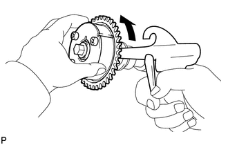
(5) Remove the vinyl tape and rubber pieces from the camshaft.
(f) Remove the bolt and camshaft timing gear assembly.
NOTICE:
Do not allow the camshaft timing gear assembly to lock. If it locks, release the lock pin again.
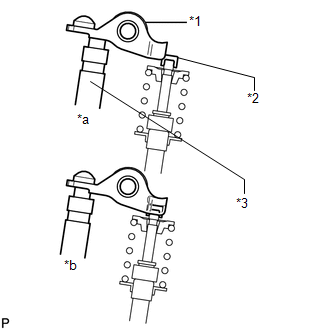
7. INSTALL VALVE LASH ADJUSTER ASSEMBLY
(a) Inspect the valve lash adjuster assemblies before installing them (See page
).
(b) Install the 16 valve lash adjuster assemblies to the cylinder head sub-assembly.
NOTICE:
Install each valve lash adjuster assembly to the same place it was removed from.
8. INSTALL NO. 1 VALVE ROCKER ARM SUB-ASSEMBLY
|
(a) Apply engine oil to the valve lash adjuster assembly tips and valve stem caps. Text in Illustration
|
|
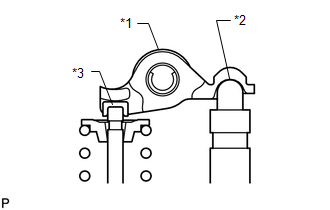
(b) Install the 16 No. 1 valve rocker arm sub-assemblies as shown in the illustration.
9. INSTALL NO. 2 CAMSHAFT BEARING
10. INSTALL NO. 1 CAMSHAFT BEARING
11. INSTALL OIL CONTROL VALVE FILTER
12. INSTALL CAMSHAFT
(a) Clean the camshaft journals, camshaft housing sub-assembly and camshaft bearing caps.
(b) Apply a light coat of engine oil to the camshaft journal, camshaft housing sub-assembly and camshaft bearing caps.
(c) Install the No. 1 camshaft and No. 2 camshaft to the camshaft housing sub-assembly.
HINT:
Perform "Inspection After Repair" after replacing the No. 1 camshaft or No. 2
camshaft (See page ).
13. INSTALL CAMSHAFT BEARING CAP
|
(a) Confirm the marks and numbers on the camshaft bearing caps and place them in their proper positions and directions. |
|
|
(b) Install the 11 bolts in the order shown in the illustration. Torque: 16 N·m {163 kgf·cm, 12 ft·lbf} NOTICE: Make sure that the camshaft rotates smoothly after installing the camshaft bearing caps. |
|
14. INSTALL CAMSHAFT HOUSING SUB-ASSEMBLY
|
(a) Check that the valve rocker arms are installed as shown in the illustration. Text in Illustration
|
|
|
(b) Apply seal packing in a continuous line as shown in the illustration. Text in Illustration
Seal Packing: Toyota Genuine Seal Packing Black, Three Bond 1207B or equivalent Standard Seal Dimension:
NOTICE:
|
|
|
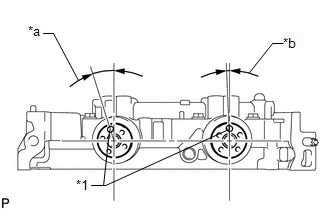
(c) Position the knock pin of the No. 1 camshaft and No. 2 camshaft as shown in the illustration. Text in Illustration
|
|
|
(d) Install the camshaft housing sub-assembly, and then install the 20 bolts in the order shown in the illustration. Torque: 27 N·m {275 kgf·cm, 20 ft·lbf} NOTICE:
|
|
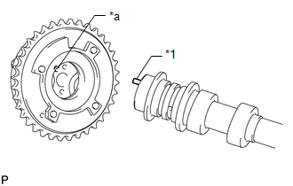
15. INSTALL CAMSHAFT TIMING GEAR ASSEMBLY
|
(a) Check the camshaft timing gear assembly position. Text in Illustration
If the camshaft timing gear assembly is not set to the advanced position, release the lock pin and reset the camshaft timing gear assembly (Refer to the "Set Camshaft Timing Gear Assembly" procedure). |
|
|
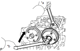
(b) Align and attach the knock pin of the No. 1 camshaft with the pin hole of the camshaft timing gear assembly. Text in Illustration
|
|
|
(c) Check that there is no clearance between the camshaft timing gear assembly and camshaft flange. Text in Illustration
|
|
|
(d) Using a wrench to hold the hexagonal portion of the No. 1 camshaft, install the bolt. Text in Illustration
Torque: 85 N·m {867 kgf·cm, 63 ft·lbf} NOTICE:
HINT: Perform "Inspection After Repair" after replacing the camshaft timing
gear assembly (See page |
|
16. INSTALL CAMSHAFT TIMING EXHAUST GEAR ASSEMBLY
|
(a) Align and attach the knock pin of the No. 2 camshaft with the pin hole of the camshaft timing exhaust gear assembly. Text in Illustration
|
|
|
(b) Check that there is no clearance between the camshaft timing exhaust gear assembly and camshaft flange. Text in Illustration
|
|
|
(c) Using a wrench to hold the hexagonal portion of the No. 2 camshaft, install the bolt. Text in Illustration
Torque: 85 N·m {867 kgf·cm, 63 ft·lbf} NOTICE:
HINT: Perform "Inspection After Repair" after replacing the camshaft timing
exhaust gear assembly (See page |
|
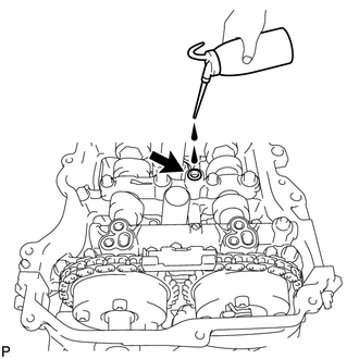
17. ADD ENGINE OIL
|
(a) Add 50 cc (3.1 cu. in) of engine oil into the oil hole shown in the illustration. NOTICE:
|
|
18. SET NO. 1 CYLINDER TO TDC/COMPRESSION
|
(a) Temporarily install the crankshaft pulley bolt. |
|
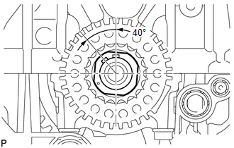
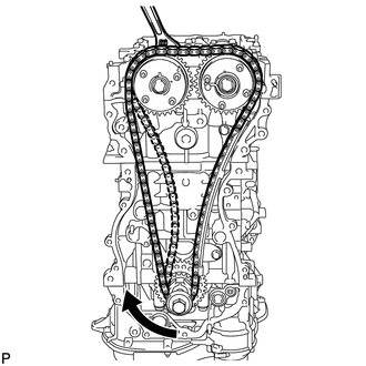
(b) Rotate the crankshaft 40° counterclockwise to position the crankshaft pulley key as shown in the illustration.
|
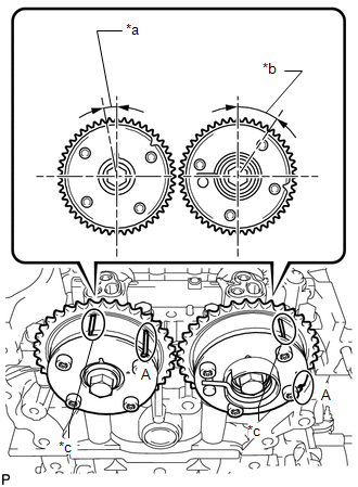
(c) Check that the timing marks of the camshaft timing gear assembly and camshaft timing exhaust gear assembly are as shown in the illustration. Text in Illustration
HINT: "A" is not a timing mark. |
|
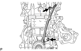
19. INSTALL NO. 1 CHAIN VIBRATION DAMPER
|
(a) Install the No. 1 chain vibration damper with the 2 bolts in the order shown in the illustration. Torque: 21 N·m {214 kgf·cm, 15 ft·lbf} |
|
20. INSTALL CHAIN SUB-ASSEMBLY
(a) Place the chain sub-assembly onto the camshaft timing gear assembly, camshaft timing exhaust gear assembly and crankshaft timing sprocket.
HINT:
- Make sure the mark plate of the chain sub-assembly faces away from the engine.
- It is not necessary to install the chain sub-assembly to the teeth of the camshaft timing gear assembly, camshaft timing exhaust gear assembly and crankshaft timing sprocket.
|
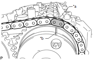
(b) Align the mark plate (yellow or gold) of the chain sub-assembly with the timing mark of the camshaft timing exhaust gear assembly and install the chain sub-assembly to the camshaft timing exhaust gear assembly. Text in Illustration
|
|
|
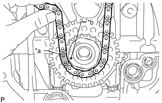
(c) Align the mark plate (pink or gold) of the chain sub-assembly with the timing mark of the crankshaft timing sprocket and install the chain sub-assembly to the crankshaft timing sprocket. Text in Illustration
|
|
|
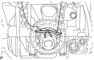
(d) Tie a string above the crankshaft timing sprocket to secure the chain sub-assembly. |
|
|
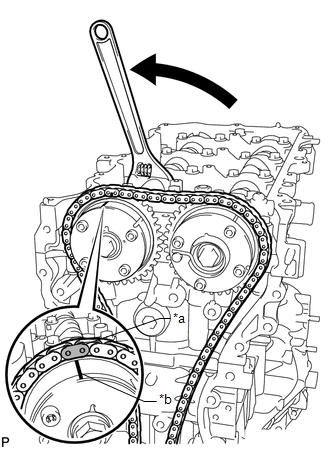
(e) Using the hexagonal portion of the No. 1 camshaft, rotate the No. 1 camshaft counterclockwise with a wrench, align the timing mark of the camshaft timing gear assembly with the mark plate (yellow or gold) of the chain sub-assembly and install the chain sub-assembly to the camshaft timing gear assembly. Text in Illustration
HINT: Hold the No. 1 camshaft in place with a wrench until the No. 1 chain tensioner assembly is installed. |
|
|
(f) Remove the string above the crankshaft timing sprocket, rotate the crankshaft clockwise, and loosen the chain sub-assembly so that the chain tensioner slipper can be installed. NOTICE: Make sure the chain sub-assembly is secure. |
|
21. INSTALL CHAIN TENSIONER SLIPPER
|
(a) Install the chain tensioner slipper with the bolt. Torque: 21 N·m {214 kgf·cm, 15 ft·lbf} |
|
.png)
22. INSTALL NO. 1 CHAIN TENSIONER ASSEMBLY
|
(a) Install a new gasket and the No. 1 chain tensioner assembly with the 2 bolts. Torque: 10 N·m {102 kgf·cm, 7 ft·lbf} |
|
.png)
(b) Remove the pin from the stopper plate.
23. INSTALL TIMING CHAIN GUIDE
|
(a) Install the timing chain guide with the bolt Torque: 21 N·m {214 kgf·cm, 15 ft·lbf} |
|
.png)
24. CHECK NO. 1 CYLINDER TO TDC/COMPRESSION
(a) Temporarily install the crankshaft pulley bolt.
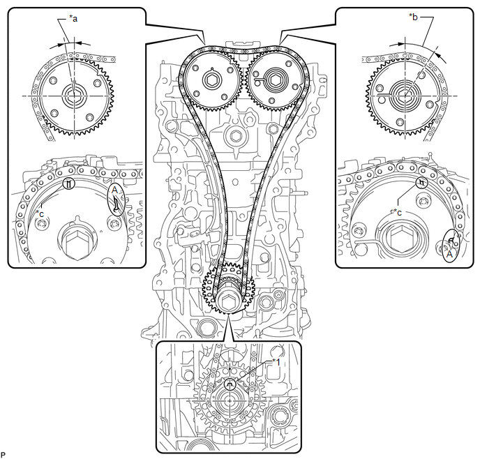 Text in Illustration
|
*1 |
Crankshaft Pulley Set Key |
- |
- |
|
*a |
Approximately 7° |
*b |
Approximately 32° |
|
*c |
Timing Mark |
- |
- |
(b) Rotate the crankshaft clockwise and align the crankshaft pulley set key as shown in the illustration.
HINT:
"A" is not a timing mark.
(c) Check that the timing marks on the camshaft timing gear assembly and camshaft timing exhaust gear assembly are as shown in the illustration.
(d) Remove the crankshaft pulley bolt.
25. INSTALL TIMING CHAIN COVER SUB-ASSEMBLY
(See page )
26. INSTALL INTAKE MANIFOLD
27. CONNECT NO. 2 VENTILATION HOSE
28. INSTALL FUEL DELIVERY PIPE SUB-ASSEMBLY
29. INSTALL THROTTLE BODY ASSEMBLY
30. INSTALL EXHAUST MANIFOLD CONVERTER SUB-ASSEMBLY
(a) Install the exhaust manifold converter sub-assembly (See page
).
31. INSTALL ENGINE ASSEMBLY WITH TRANSAXLE
(a) Install the engine assembly with transaxle (See page
).
 Removal
REMOVAL
PROCEDURE
1. REMOVE ENGINE ASSEMBLY WITH TRANSAXLE
(a) Remove the engine and transaxle (See page
).
2. REMOVE EXHAUST MANIFOLD CONVERTER SUB-ASSEMBLY
(a) Remove the exhaust manifold con ...
 Drive Belt
Components
COMPONENTS
ILLUSTRATION
On-vehicle Inspection
ON-VEHICLE INSPECTION
PROCEDURE
1. INSPECT V-RIBBED BELT
(a) Check the belt for wear, cracks or other signs of damage.
...
Other materials about Toyota Venza:
Seat belts
Make sure that all occupants are wearing their seat belts before driving the
vehicle.
- Correct use of the seat belts
1. Extend the shoulder belt so that it comes fully over the shoulder, but does
not come into contact with the neck or slide off ...
Short in Passenger Side Airbag Variable Vent Hole Squib Circuit (B181A/7A-B181D/7A)
DESCRIPTION
The passenger side airbag variable vent hole squib circuit consists of the center
airbag sensor assembly and front passenger airbag assembly.
The center airbag sensor assembly uses this circuit to deploy the airbag when
deployment conditions ...
Driver Side Door ECU Communication Stop (B2321)
DESCRIPTION
This DTC is stored when LIN communication between the power window regulator
motor assembly (for driver side) and main body ECU (driver side junction block assembly)
stops for more than 10 seconds.
DTC No.
DTC Detection ...

0.1302