Toyota Venza: Components
COMPONENTS
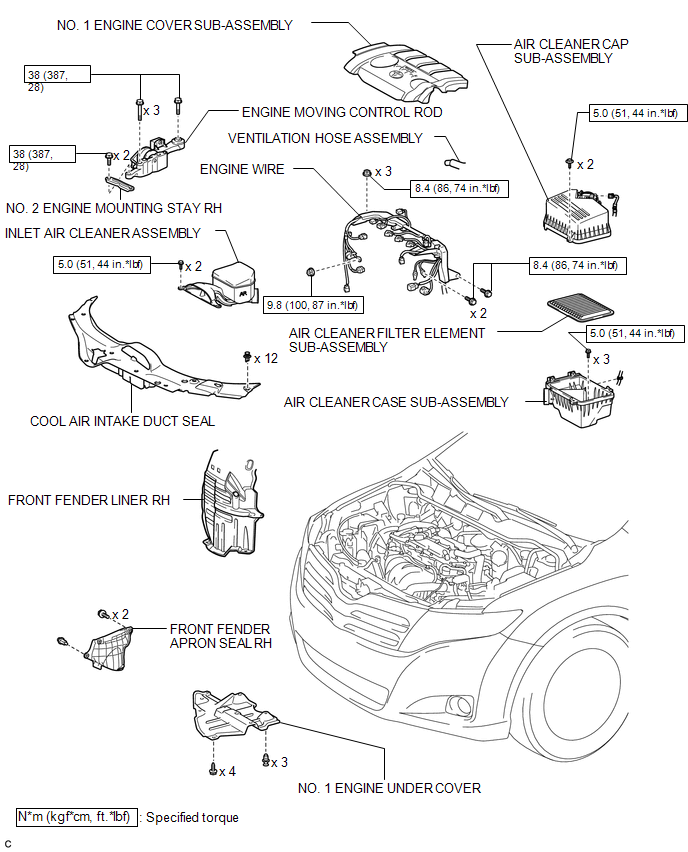
ILLUSTRATION
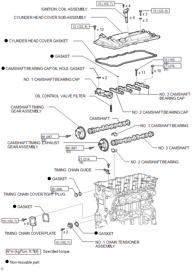
ILLUSTRATION
 Camshaft
...
 Removal
REMOVAL
PROCEDURE
1. DISCONNECT CABLE FROM NEGATIVE BATTERY TERMINAL
NOTICE:
When disconnecting the cable, some systems need to be initialized after the cable
is reconnected (See page ).
2. RE ...
Other materials about Toyota Venza:
Brake fluid
- Checking fluid level
The brake fluid level should be between the “MAX” and “MIN” lines on the tank.
Make sure to check the fluid type and prepare the necessary items.
- Adding fluid
- Brake fluid can absorb moisture from the ...
Front Speed Sensor RH Circuit (C0200/31,C0205/32,C1271/71,C1272/72,C1330/35,C1331/36)
DESCRIPTION
The speed sensor detects wheel speed and sends the appropriate signals to the
skid control ECU. These signals are used for the ABS control system.
Speed sensor rotors have 48 serrations. The hall IC type speed sensor use the
frequency of outp ...
Compass
The compass on the inside rear view mirror indicates the direction in which
the vehicle is heading.
- Operation
To turn the compass on or off, push and hold “AUTO” for longer than 3 seconds.
- Displays and directions
Calibrating the c ...

0.1913