Toyota Venza: Relay
On-vehicle Inspection
ON-VEHICLE INSPECTION
PROCEDURE
1. INSPECT STARTER RELAY
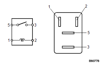
|
(a) Measure the resistance according to the value(s) in the table below. Standard Resistance:
If the resistance is not as specified, replace the relay. |
|
 Ignition Switch
Components
COMPONENTS
ILLUSTRATION
Removal
REMOVAL
PROCEDURE
1. REMOVE LOWER STEERING COLUMN COVER
2. REMOVE UPPER STEERING COLUMN COVER
3. REMOVE IGNITION SWITCH
(a) R ...
 Starter
...
Other materials about Toyota Venza:
Lost Communication with Rear Gate Module (U0230)
DESCRIPTION
DTC No.
DTC Detection Condition
Trouble Area
U0230
No communication from the power back door ECU (back door motor unit)
or back door closer ECU continues.
Power ...
How To Proceed With Troubleshooting
CAUTION / NOTICE / HINT
HINT:
Use the following procedure to troubleshoot the windshield deicer system.
PROCEDURE
1.
VEHICLE BROUGHT TO WORKSHOP
NEXT
...
System Description
SYSTEM DESCRIPTION
1. FUNCTION OF MAIN COMPONENTS
Component
Function
Accessory Meter Assembly
AWD Warning Light
Illuminates to warn the driver of a malfunction in the active
torque ...

0.1758