Toyota Venza: Ignition Switch
Components
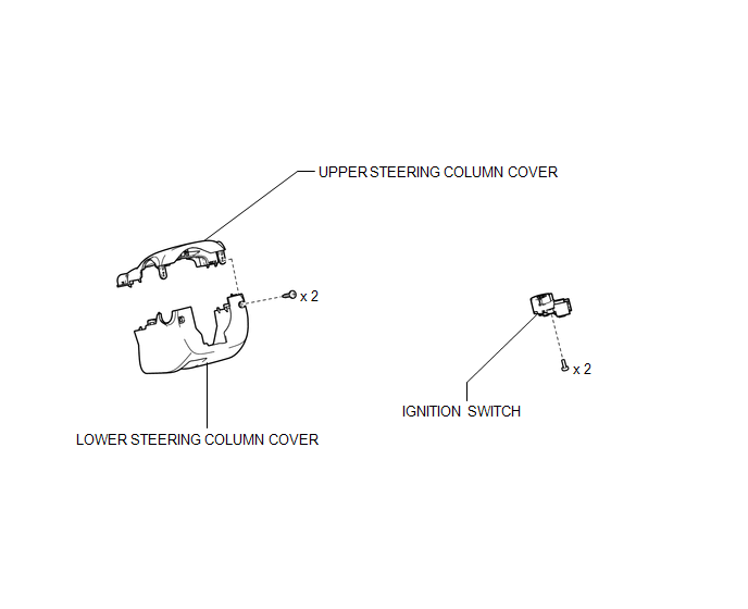
COMPONENTS
ILLUSTRATION
Removal
REMOVAL
PROCEDURE
1. REMOVE LOWER STEERING COLUMN COVER
.gif)
2. REMOVE UPPER STEERING COLUMN COVER
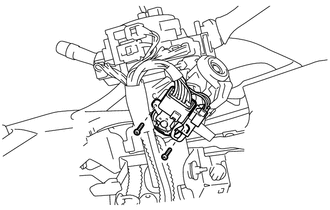
3. REMOVE IGNITION SWITCH
|
(a) Remove the 2 screws and ignition switch. |
|
|
(b) Disconnect the connector. |
|
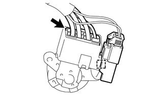
(c) Disconnect the connector clamp from the ignition switch.
Inspection
INSPECTION
PROCEDURE
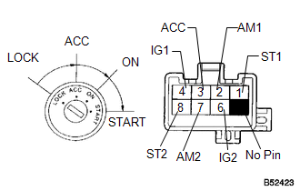
1. INSPECT IGNITION SWITCH
|
(a) Measure the switch resistance. Standard Resistance:
If the result is not as specified, replace the switch assembly. |
|
Installation
INSTALLATION
PROCEDURE
1. INSTALL IGNITION SWITCH
|
(a) Connect the connector. |
|
.png)
(b) Install the connector clamp to the ignition switch.
|
(c) Install the ignition switch with the 2 screws. |
|
.png)
2. INSTALL UPPER STEERING COLUMN COVER
.gif)
3. INSTALL LOWER STEERING COLUMN COVER
 Installation
INSTALLATION
PROCEDURE
1. INSTALL ENGINE SWITCH
(a) Attach the 2 claws to install the engine switch.
2. INSTALL LOWER INSTRUMENT PANEL FI ...
 Relay
Relay
On-vehicle Inspection
ON-VEHICLE INSPECTION
PROCEDURE
1. INSPECT STARTER RELAY
(a) Measure the resistance according to the value(s) in the table below.
Standard Resistance:
...
Other materials about Toyota Venza:
Tire Pressure Warning Light Circuit
DESCRIPTION
If the tire pressure warning ECU detects a malfunction, the tire pressure warning
light blinks for 1 minute then stays on and tire pressure monitor is canceled at
the same time. At this time, the ECU records a DTC in the memory.
Connecting te ...
Components
COMPONENTS
ILLUSTRATION
ILLUSTRATION
ILLUSTRATION
ILLUSTRATION
ILLUSTRATION
...
Power Seat Power Easy Access System Function does not Operate
DESCRIPTION
When the ignition switch is off and shift lever is in P, the power seat slides
rearward when the seat belt tongue plate is disengaged from the front seat inner
belt assembly LH (auto away function). Also the power seat slides forward when the ...

0.1398