Toyota Venza: Reassembly
REASSEMBLY
PROCEDURE
1. INSTALL FRONT BLOWER MOTOR SUB-ASSEMBLY
|
(a) Install the front blower motor sub-assembly with the 3 screws. |
|
.png)
2. INSTALL AIR INLET SERVO MOTOR SUB-ASSEMBLY
|
(a) Install the air inlet servo motor sub-assembly with the 3 screws. |
|
.png)
|
(b) Engage the 6 claws. |
|
.png)
(c) install the blower case with the screw.
3. INSTALL AIR CONDITIONING AMPLIFIER ASSEMBLY
|
(a) Install the air conditioning amplifier assembly with the 2 screws. |
|
.png)
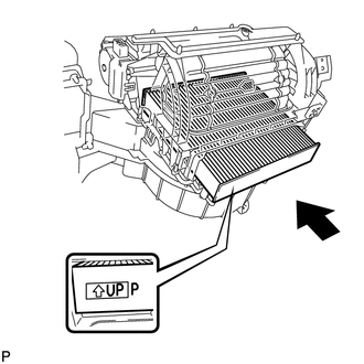
4. INSTALL CLEAN AIR FILTER
|
(a) Install the clean air filter as shown in the illustration. |
|
5. INSTALL AIR FILTER COVER PLATE
|
(a) Engage the 2 claws to install the air filter cover plate. |
|
.png)
6. INSTALL NO. 1 AIR DUCT SUB-ASSEMBLY
|
(a) Engage the 4 claws to install the No. 1 air duct sub-assembly. |
|
.png)
 Disassembly
DISASSEMBLY
PROCEDURE
1. REMOVE NO. 1 AIR DUCT SUB-ASSEMBLY
(a) Disengage the 4 claws and remove the No. 1 air duct sub-assembly.
2. REMOV ...
 Installation
INSTALLATION
PROCEDURE
1. INSTALL NO. 1 COOLER THERMISTOR
2. INSTALL COOLER EVAPORATOR SUB-ASSEMBLY
3. INSTALL BLOWER ASSEMBLY WITH COOLER EVAPORATOR SUB-ASSEMBLY
(a) Engage the 5 claws.
( ...
Other materials about Toyota Venza:
Installation
INSTALLATION
PROCEDURE
1. INSTALL NO. 1 ULTRASONIC SENSOR RETAINER
(a) Engage the 2 claws to install the No. 1 ultrasonic sensor retainer
to the rear bumper assembly.
Text in Illustration
*A
LH Side
...
Camshaft Position Sensor Circuit Malfunction (P0340,P0342,P0343)
DESCRIPTION
The camshaft position sensor (G signal sensor) for the intake camshaft consists
of a magnet and MRE (Magneto Resistance Element).
The camshaft has a timing rotor for the camshaft position sensor. When the camshaft
rotates, changes occur in th ...
Inspection
INSPECTION
PROCEDURE
1. INSPECT REAR NO. 3 SPEAKER ASSEMBLY (for 13 Speakers)
(a) With the speaker installed, check that there is no looseness or other abnormalities.
(b) Check that there is no foreign matter in the speaker, no tears on the speaker
cone ...

0.1379