Toyota Venza: Afs Ecu
Components
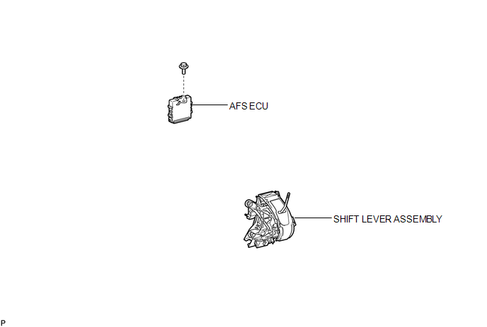
COMPONENTS
ILLUSTRATION
Installation
INSTALLATION
PROCEDURE
1. INSTALL AFS ECU
|
(a) Engage the guide. |
|
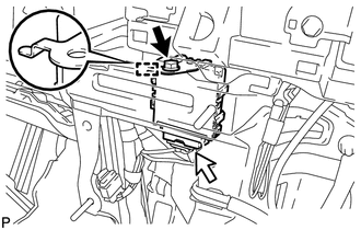
(b) Install the AFS ECU with the bolt.
(c) Connect the connector.
2. INSTALL SHIFT LEVER ASSEMBLY (for 2WD)
HINT:
Refer to the procedure from Install Shift Lever Assembly (See page
.gif) ).
).
3. INSTALL SHIFT LEVER ASSEMBLY (for AWD)
HINT:
Refer to the procedure from Install Shift Lever Assembly (See page
).
Removal
REMOVAL
PROCEDURE
1. REMOVE SHIFT LEVER ASSEMBLY (for 2WD)
HINT:
Refer to the procedure up to Remove Shift Lever Assembly (See page
.gif) ).
).
2. REMOVE SHIFT LEVER ASSEMBLY (for AWD)
HINT:
Refer to the procedure up to Remove Shift Lever Assembly (See page
).
3. REMOVE AFS ECU
|
(a) Disconnect the connector. |
|
.png)
(b) Remove the bolt.
(c) Disengage the guide and remove the AFS ECU.
 Lighting (ext)
...
 Automatic Light Control Sensor
Components
COMPONENTS
ILLUSTRATION
Removal
REMOVAL
PROCEDURE
1. REMOVE DEFROSTER NOZZLE GARNISH
2. REMOVE AUTOMATIC LIGHT CONTROL SENSOR
(a) Disengage the 2 claws and remov ...
Other materials about Toyota Venza:
Installation
INSTALLATION
PROCEDURE
1. INSTALL STARTER ASSEMBLY
(a) Install the starter with the 2 bolts.
Torque:
37 N·m {377 kgf·cm, 27 ft·lbf}
(b) Connect the starter connector.
...
Removal
REMOVAL
PROCEDURE
1. DISCONNECT CABLE FROM NEGATIVE BATTERY TERMINAL
NOTICE:
When disconnecting the cable, some systems need to be initialized after the cable
is reconnected (See page ).
2. REMOVE UPPER CONSOLE PANEL SUB-ASSEMBLY (w/o Seat Heater Syste ...
Inspection
INSPECTION
PROCEDURE
1. INSPECT PAD LINING THICKNESS
(a) Using a ruler, measure the pad lining thickness.
Text in Illustration
*1
Ruler
Standard thickness of a new pad:
10.0 mm (0.394 ...

0.1589