Toyota Venza: Installation
INSTALLATION
PROCEDURE
1. INSTALL OUTER REAR VIEW MIRROR ASSEMBLY
|
(a) Engage the 3 claws to install the outer rear view mirror assembly as shown in the illustration. |
|
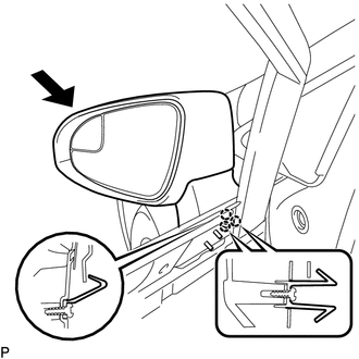
(b) Install the 3 nuts.
Torque:
8.0 N·m {82 kgf·cm, 71 in·lbf}
(c) Connect the connector.
(d) Install the hole plug.
2. INSTALL FRONT DOOR SERVICE HOLE COVER
.gif)
3. INSTALL OUTER MIRROR CONTROL ECU ASSEMBLY (w/ Memory)
4. INSTALL DOOR SIDE AIRBAG SENSOR
5. INSTALL FRONT DOOR INSIDE HANDLE SUB-ASSEMBLY
6. INSTALL FRONT DOOR TRIM BOARD SUB-ASSEMBLY
7. INSTALL COURTESY LIGHT ASSEMBLY
8. INSTALL POWER WINDOW REGULATOR MASTER SWITCH ASSEMBLY WITH FRONT DOOR ARMREST BASE PANEL (for Driver Side)
9. INSTALL POWER WINDOW REGULATOR SWITCH ASSEMBLY WITH FRONT DOOR ARMREST BASE PANEL (for Front Passenger Side)
10. INSTALL FRONT DOOR INSIDE HANDLE BEZEL PLUG
11. CONNECT CABLE TO NEGATIVE BATTERY TERMINAL
NOTICE:
When disconnecting the cable, some systems need to be initialized after the cable
is reconnected (See page ).
12. INSPECT SRS WARNING LIGHT
(See page )
 Reassembly
REASSEMBLY
PROCEDURE
1. INSTALL SIDE TURN SIGNAL LIGHT ASSEMBLY
2. INSTALL OUTER MIRROR COVER
3. INSTALL OUTER MIRROR LIGHT ASSEMBLY
4. INSTALL OUTER MIRROR
...
 Outer Rear View Mirror Cover
Components
COMPONENTS
ILLUSTRATION
Installation
INSTALLATION
PROCEDURE
1. INSTALL OUTER MIRROR COVER
(a) Engage the 7 claws to install the outer mirror cover.
...
Other materials about Toyota Venza:
Crankshaft Position Sensor
Components
COMPONENTS
ILLUSTRATION
Removal
REMOVAL
PROCEDURE
1. REMOVE FRONT FENDER APRON SEAL RH
2. REMOVE CRANKSHAFT POSITION SENSOR
(a) Disconnect the sensor connector.
(b) Remove the bolt and sensor.
Inspection
INSPECTION
PROCEDURE ...
High Mounted Stop Light Assembly
Components
COMPONENTS
ILLUSTRATION
Removal
REMOVAL
PROCEDURE
1. REMOVE CENTER STOP LIGHT ASSEMBLY
(a) Using a short screwdriver, remove the 2 screws.
(b) Disconnect the connector and remov ...
Initialization
INITIALIZATION
1. RESET BACK DOOR CLOSE POSITION (w/ POWER BACK DOOR SYSTEM)
NOTICE:
Perform initialization of the power back door system (power back door ECU initialization)
if one of the following is performed:
The cable is disconnected from the ...

0.1753