Toyota Venza: Installation
INSTALLATION
PROCEDURE
1. INSTALL FUEL SUCTION TUBE ASSEMBLY WITH PUMP AND GAUGE
(a) Install a new fuel suction tube set gasket onto the fuel tank.
|
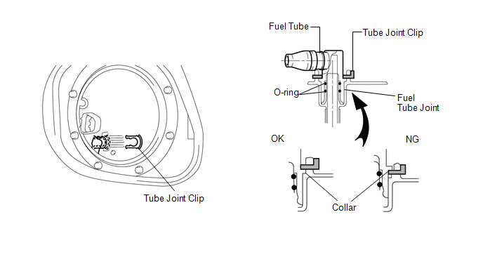
(b) Connect the fuel tube with the clip. |
|
.png)
(c) Set the fuel suction tube assembly to the fuel tank.
NOTICE:
- Be careful not to bend the arm of the fuel sender gauge.
- Do not damage the fuel tube.
|
(d) Align the protrusion of the fuel suction tube assembly with pump and gauge and the cutout of the fuel tank vent tube set plate. |
|
.png)
(e) While holding the fuel suction with pump and gauge tube assembly by hand, install the fuel tank vent tube to the fuel tank with the 8 bolts.
Torque:
6.0 N·m {61 kgf·cm, 53 in·lbf}
(f) Install the fuel tank main tube sub-assembly and the tube joint clip.
NOTICE:
- Check that there are no scratches or foreign matter around the connected part of the fuel tube joint and plug before performing this work.
- Check that the fuel tube joint is securely inserted.
- Check that the tube joint clip is on the collar of the fuel tube joint.
- After installing the tube joint clip, check that the fuel tube cannot be pulled out.
|
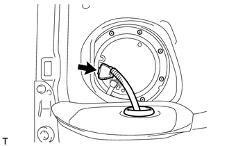
(g) Connect the fuel pump connector. |
|
2. CONNECT CABLE TO NEGATIVE BATTERY TERMINAL
NOTICE:
When disconnecting the cable, some systems need to be initialized after the cable
is reconnected (See page .gif) ).
).
3. INSPECT FOR FUEL LEAK
4. INSTALL REAR FLOOR SERVICE HOLE COVER
|
(a) Install the rear floor service hole cover with new butyl tape. |
|
(b) Install the rear floor carpet and the rear floor silencer.
5. INSTALL REAR SEAT ASSEMBLY LH
(a) Install the rear seat assembly LH (See page
).
6. INSTALL REAR SEAT ASSEMBLY RH
(a) Install the rear seat assembly RH (See page
).
 Reassembly
REASSEMBLY
PROCEDURE
1. INSTALL FUEL PUMP ASSEMBLY WITH FILTER
HINT:
Perform "Inspection After Repair" after replacing the fuel pump (See page
).
(a) Apply gasoline to a ne ...
 Fuel Sender Gauge Assembly
Components
COMPONENTS
ILLUSTRATION
Removal
REMOVAL
PROCEDURE
1. DISCHARGE FUEL SYSTEM PRESSURE
(a) Discharge fuel system pressure (See page
).
2. DISCONNECT CABLE FROM NEGATIVE BATTERY ...
Other materials about Toyota Venza:
Vehicle Speed Sensor Malfunction (B2415)
DESCRIPTION
The AFS ECU (headlight swivel ECU assembly) receives signals indicating the front
right wheel speed from the skid control ECU using CAN communication.
DTC No.
DTC Detection Condition
Trouble Area
...
Removal
REMOVAL
PROCEDURE
1. PRECAUTION
CAUTION:
Be sure to read Precaution thoroughly before servicing (See page
).
If the front seat side airbag assembly was deployed, replace the front
seat side airbag assembly, front seat frame assembly wit ...
Front Lower Suspension Arm(when Using The Engine Support Bridge)
Components
COMPONENTS
ILLUSTRATION
Removal
REMOVAL
CAUTION / NOTICE / HINT
HINT:
Use the same procedure for the LH side and RH side.
The following procedure is for the LH side.
PROCEDURE
1. REMOVE FRONT FRAME ASSEMBLY
for 1AR- ...

0.1361