Toyota Venza: Inspection
INSPECTION
PROCEDURE
1. INSPECT DRIVE MONITOR SWITCH
(a) Measure the resistance according to the value(s) in the table below.
Standard Resistance:
|
Tester Connection |
Condition |
Specified Condition |
|---|---|---|
|
3 (E) - 5 (INFO) |
INFO CLOCK*1 or INFO*2 switch is pressed |
Below 1 Ω |
|
3 (E) - 5 (INFO) |
INFO CLOCK*1 or INFO*2 switch is released |
10 kΩ or higher |
|
3 (E) - 6 (SEL) |
RESET H *1 or SELECT RESET*2 switch is pressed |
Below 1 Ω |
|
3 (E) - 6 (SEL) |
RESET H *1 or SELECT RESET*2 switch is released |
10 kΩ or higher |
|
3 (E) - 7 (STUP) |
US/M M*1 or SETUP*2 switch is pressed |
Below 1 Ω |
|
3 (E) - 7 (STUP) |
US/M M*1 or SETUP*2 switch is released |
10 kΩ or higher |
- *1: w/o Rear View Monitor System
- *2: w/ Rear View Monitor System
(b) Apply battery voltage from the wire harness back side between the terminals of the switch, and check the lighting condition of the drive monitor switch.
OK:
|
Measurement Condition |
Condition |
Specified Condition |
|---|---|---|
|
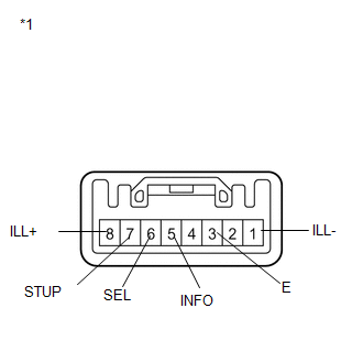
Battery negative (-) → 1 (ILL-) Battery positive (+) → 8 (ILL+) |
Always |
Drive monitor switch illuminates |
|
*1 |
Component without harness connected (Drive Monitor Switch) |
HINT:
If the result is not as specified, replace the drive monitor switch (See page
.gif) ).
).
 Components
COMPONENTS
ILLUSTRATION
ILLUSTRATION
ILLUSTRATION
...
 Removal
REMOVAL
PROCEDURE
1. REMOVE UPPER CONSOLE PANEL SUB-ASSEMBLY (w/o Seat Heater System)
2. REMOVE UPPER CONSOLE PANEL SUB-ASSEMBLY (w/ Seat Heater System)
3. REMOVE NO. 2 CONSOLE BOX CARPET
...
Other materials about Toyota Venza:
Installation
INSTALLATION
CAUTION / NOTICE / HINT
HINT:
Perform "Inspection After Repair" after replacing the engine assembly (See page
).
PROCEDURE
1. INSTALL ENGINE HANGERS
2. REMOVE ENGINE STAND
(a) Remove the engine stand.
3. INSTALL ENGINE WIRE
...
System Diagram
SYSTEM DIAGRAM
Communication Table
Sender
Receiver
Signal
Line
Main Body ECU
(Driver Side Junction Block Assembly)
Clearance Warning ECU Assembly
Destination information
...
Lost Communication with ECM / PCM "A" (U0100)
DESCRIPTION
The engine control unit communicates with the TCM using the Controller Area Network
(CAN).
If there is a problem in this communication, the TCM sets a DTC.
DTC No.
DTC Detection Condition
Trouble Area
...

0.1159